HID Aero X1100 Panduan Instalasi - Halaman 4
Jelajahi secara online atau unduh pdf Panduan Instalasi untuk Pengontrol HID Aero X1100. HID Aero X1100 8 halaman. Intelligent controller
Powering
Trusted Identities
5.
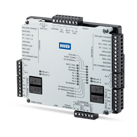
Relay circuit wiring
Four relays are provided for controlling door lock
mechanisms or alarm signaling.
When controlling the delivery of power to the door
strike, the NO (Normally Open) and C (Common) poles
are typically used.
When momentarily removing power to unlock the door,
as with a mag lock, the NC (Normally Closed) and C
(Common) poles are typically used.
Check with local building codes for proper egress door
installation.
CAUTION
Door lock mechanisms can generate feedback to the
relay circuit. This can cause damage and premature
failure of the relay, effecting the operation of the
X1100. Use a diode to protect the relay. Use a wire of
sufficient gauge to avoid voltage loss.
6.
DIP switch configuration
The four DIP switches are used to configure the
operating mode of the X1100 processor. DIP switches
are read on power-up except where noted.
Press RESET switch to reboot the X1100.
1
2
3
4
OFF OFF OFF OFF Normal operating mode.
ON
X
OFF OFF
OFF
ON
OFF OFF Use factory default communication parameters.
ON
ON
OFF OFF Bulk Erase prompt mode at power up. See page 5.
Note: All other switch settings are unassigned and are reserved for future use. X = don't care.
Note: In the factory default modes, the downloaded configuration/database is not saved to flash memory.
Factory default communication parameters
Network: static IP address: 192.168.0.251
Subnet Mask: 255.255.0.0
Default Gateway: 192.168.0.1
DNS Server: 192.168.0.1
7.
Input circuit wiring
Inputs are typically used for the following:
To monitor door position.
Request to exit.
Alarm contacts.
Input IN 1 to IN 4 circuits can be configured as
unsupervised or supervised and can use normally open
or normally closed contacts.
For a supervised circuit, add two 1KΩ, 1% resistors as
close to the sensor as possible.
Custom end of line (EOL) resistances may be configured
via the host software.
4
After initialization, enable default User Name (admin) and Password (password). The
switch is read on the fly, no need to re-boot. For additional information, See page 5.
HID Aero™ X1100 Installation Guide
DC Strike
To DC power source
-
Diode
+
Diode selection:
Diode current rating: 1x strike current.
Diode breakdown voltage: 4x strike voltage.
For 12 V DC or 24 V DC strike, diode 1N4002
(100V/1A) typical.
DEFINITIONS
Primary Host port: IP server, Data Security: TLS if
Available, port 3001, communication address: 0
Alternate Host Port: Disabled
Unsupervised circuit IN 1 to IN 4
Supervised circuit IN 1 to IN 4
1K,1%
1K,1%
Note: The input circuit wiring configurations shown are
supported but may not be typical.
- +
RELAY 1 to
RELAY 4
Fuse
PLT-04233, Rev. A.3