Hideaway Concelo CR350-216 Petunjuk Instalasi - Halaman 2
Jelajahi secara online atau unduh pdf Petunjuk Instalasi untuk Perabotan Dalam Ruangan Hideaway Concelo CR350-216. Hideaway Concelo CR350-216 4 halaman.
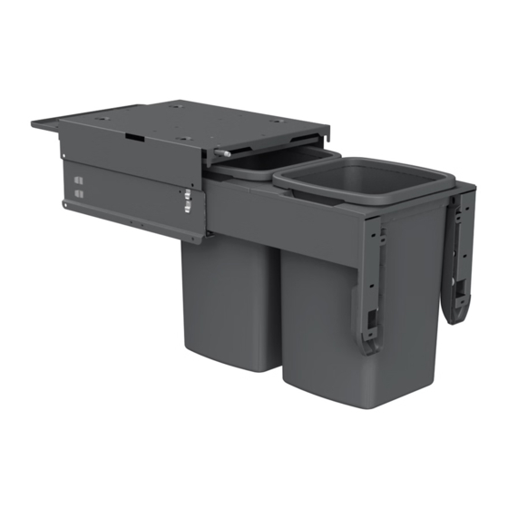
FIG.1
Collar Rear
Panel
Collar Side Sub Assembly
PLEASE WATCH THE INSTALL VIDEO BEFORE YOU BEGIN
Step 1 – Unpack carton
• Unpack all components from carton.
• Be careful not to dispose of Active Lid which is packed
inside an inner carton.
Step 2 – Pre-drill door panel
• If drilling the door panel using a CNC machine, drilling
positions are available as a CAD file from the Hideaway
Bins website.
• If drilling manually, refer to drilling template or drilling
dimensions.
• Mark a vertical centreline on the rear of the door panel.
• Mark a horizontal line indicating the top of the bin
body top reference. TIP: An allowance needs to be made
for the door overlap with the top of the carcase e.g. for a
16mm thick carcase material and 3mm gap between the
door panel and the bench top the horizontal line should be
(16-3) = 13mm down from the top edge of the panel.
• Align the door panel template with the lines as indicated
and mark the position of the mounting holes for the door
brackets through the paper. TIP: 3 screw locations
are required for each door bracket. An alternative location
for the top screw is indicated. This should only be used in
framed door situations but makes door adjustment more
difficult.
FIG.2
FIG.3
(link on the cover of these instructions)
• Drill a 2mm pilot hole at each of the mounting locations.
PLEASE NOTE: the different colour coded mounting
locations for your model - Pink = CR350 models,
Blue = CR400 models, Red = CR450 models.
Step 3 – Install collar side sub assemblies
Refer to Fig. 1
• Position collar side sub assemblies.
• Secure each using 12mm Surefix screws provided.
Step 4 – Install collar rear panel on to collar sides
Refer to Fig. 1
• Position collar rear panel as shown.
• Secure using 6G x 12mm self tapping screws.
NOTE: do not use impact driver.
Step 5 – Install body sub assembly
NOTE - For top mounting into overwidth cabinets, please
use CRTMB Top Mount Bracket Kit which is supplied
separately, and follow separate instructions for this step.
For new kitchens, where possible, it is easiest to place the
carcase upside down on a bench while installing the body.
See drilling dimensions on back of door drilling template.
FIG.4
• Refer to Fig. 2. Mark out all side mount holes referring to
drilling template.
• Predrill 5mm x 13mm deep holes for all 8 side mount holes.
• Position body in cabinet ensuring it is flush with front of
the cabinet and level. Secure to the sides of the cabinet
using 8 of the 13mm Euro screws provided.
• Refer to Fig. 3. Drill pilot holes in the front top rail of the
cabinet using the body as a guide, and secure using 3 of the
16mm Surefix screws.
Step 6 – Assemble collar and door panel to runners
• Position collar assembly as shown in Fig.4. TIP: Ensure that
runners are pulled forward, there is a black tab at the front
of the runner that can be pulled while holding the door
panel.
• Lower the door panel until a click is heard. TIP: The door
panel may need to be pushed down slightly.
• Close the product and check that it is approximately level.
TIP: If the door panel is significantly out of level it may
indicate that it is not clipped down fully on one side.
Step 7 – Adjust the door panel position
Refer to Fig. 5
• Loosen the 6 door bracket bolts using the 4mm Allen key
provided.
FIG.5
• Adjust the door to be square and parallel to carcase and in
the correct vertical position using the adjustment cams.
• Tighten the 6 door bracket bolts.
• Loosen the 6 door mounting screws and adjust the
horizontal position of the door panel, if required.
• Tighten the 6 door mounting screws.
Continue overleaf...
March 2022