Autometers Systems IC7-C Panduan Instalasi dan Pengoperasian - Halaman 2
Jelajahi secara online atau unduh pdf Panduan Instalasi dan Pengoperasian untuk Alat Ukur Autometers Systems IC7-C. Autometers Systems IC7-C 9 halaman.

The Information Centre ic
Check Contents
Package should contain:
1. Black locking bezel
2. Main meter case
3. Top terminal cover
4. Lower terminal cover
Overview
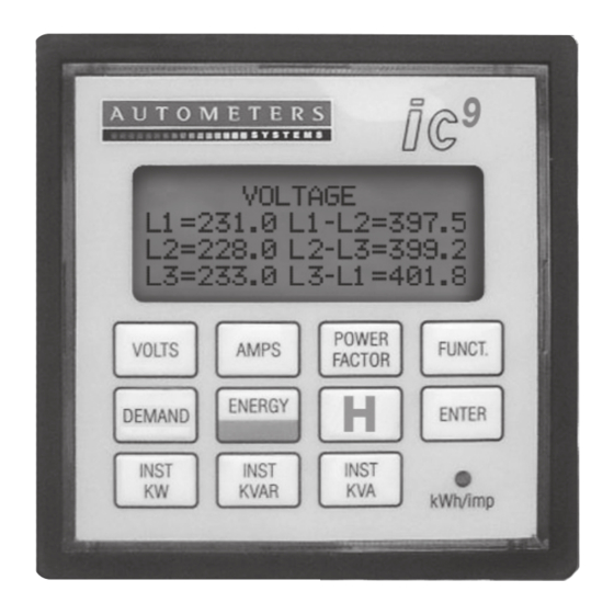
The IC7-C and IC9-C meter is
230/400 volt 50 Hz, 5 amp current
transformer operated meter
designed for measuring 3 phases
in a 4 wire star configured system
and is capable of transmitting
kWh and KVAh by means of
the volt free outputs which are
standard on the basic model. The
model IC9-C is supplied with fully
programmable RS485-Modbus
communication output and is
capable of transmitting all of the
data the meter monitors.
Installation
Orientation
The meters are designed to be
fitted into a panel, normally a
switchgear cabinet. It is therefore
recommended that the front of
16
92
16
Diagram 2. External Dimension
Diagram 1. Meter Installation
the meter is positioned vertically
with adequate space around and
at the back for connections.
Location
The meters should be mounted in
a dry dirt free environment away
from all heat sources and very
high electric fields. Temperatures
should not exceed 70°C or fall
below -20°C.
Installing the meter.
First remove the meter from the
packaging and check for any
damage. The meter should be in
two pieces, a Front Bezel and the
DILL SWITCH
DILL SWITCH
ON
DIP
Communication
Communication
1
1
2
2
3
3
4
4
5
5
6
6
7
7
8
8
Sockets
Sockets
ON
DIP
1
1
2
2
3
3
4
4
5
5
6
6
7
7
8
8
LOAD
L1
L2
L3
N
S2
P2
S1
P1
S2
P2
S1
P1
S2
P2
L2
S1
P1
S2
P2
S1
P1
L1
L2
L3
1 Amp
MAINS
230/400Volt 50Hz
0.1-5Amp
Cable Entry
Cable Entry
64
12
75
124
All Dimensions in mm
2
7
9
-C and ic
-C
back of the meter. (See diagram
1 above) The aperture required to
fit the meter is 92 mm x 92 mm.
Holding the back of the meter
in one hand and the bezel in
the other hand, present to the
opening. Slide the back of the
meter first through the opening
on the rear side of the door and
then push the bezel from the
front side over the protruding
clear plastic and push fully
home until it locks firmly.
Please note it is extremely
difficult to remove when fitted.
Please see diagram 1.
Phasing and polarity of the AC
current and voltage inputs and
their relationship is critical to the
correct operation of this meter.
The connection diagram shows a
current transformer fitted to the
Neutral.
If you do not want to monitor the
neutral current it is not necessary
to connect to terminals 7 and 8.
Terminal 9 is the Neutral supply
Terminals 10,11,and 12 are the
12
three phase line voltages (230
volt). Terminals 14,15, and 16 are
the low voltage pulse output. (volt
free)
