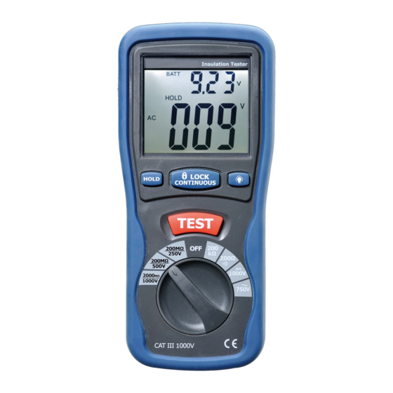
Automotive 9321280401709 Buku Petunjuk - Halaman 5
Jelajahi secara online atau unduh pdf Buku Petunjuk untuk Peralatan Uji Automotive 9321280401709. Automotive 9321280401709 7 halaman. Digital insulation tester

that subdivision of large installations might be necessary
because of the large number of parallel insulation
resistance. In such a case, an installation may be divided
into sections, each being separately tested. Each section
must have not less than fifty outlets, an outlet being a
switch, socket, lighting point etc. A switched socket
counts as one outlet. The minimum acceptable insulation
resistance is 1MΩ. For a large installation, the
capacitance of the insulation will be high, and it will take
longer for it to become charged by the direct testing
voltage. Care must be taken not to take a reading until
there is a steady reading, indicating that the charging
process is complete.
Note: The charge stored in the insulation will be discharged
automatically when the test button is released. Be
careful not to turn the range switch knob whilst the test
button is pressed, or the instrument will be damaged.
b). Measurements at 2000MΩ/1000V
Some specifications require testing at 1000V. This voltage
must also be selected where the supply voltage of the
installation is between 500V and 1000V. First, set the
range switch to 1000V and then proceed as indicated in a
above for 500V testing. The above note also applies to
testing at 1000V. In addition the following applies.
Note: Make sure that the circuit under does not include
components Which will be damaged by the 1000V
applied. Many normal components of an installation are
9
likely to be damaged if tested at 1000V. Examples are
power factor correction capacitors, low voltage mineral
insulated cables, electronic light dimmers, electronic
ballasts and starters for fluorescent lamps etc...
c). Lock power on Feature
For hands free operation a lock power on feature is
incorporated on the press to test button. Set LOCK button
to lock test voltage, Pressing it again will tester off.
5. LOW RESISTANCE (CONTINUITY)
MEASUREMENTS
a). Set the range switch to 200Ω ∙))) Position
b). Connect the red test lead to the V Ω terminal and black to
the COM terminal.
c). Connect the tips of the test leads to both ends of the
circuit under test. read resistance in Ω on the LCD.
d). When the impedance on circuit is below approximately
40Ω.It will indicate by a continuous beeper.
6. AC/DC VOLTAGE MEASUREMENTS
a). Set the range switch to ACV or DCV position
b). Connect red test lead to "V Ω" terminal and black test lead
to terminal "COM".
c). Connect test prods of test leads IN PARALLEL to the
circuit being measured.
d). Read the voltage value on LCD.
10
