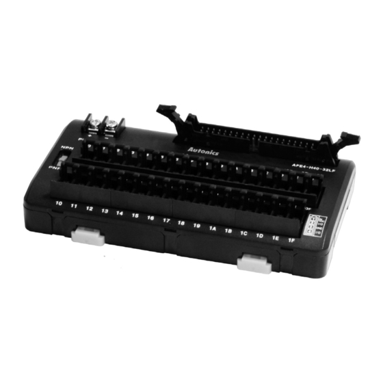
Autonics AFE4-H20-32LF Panduan Memulai Cepat - Halaman 4
Jelajahi secara online atau unduh pdf Panduan Memulai Cepat untuk Aksesori Autonics AFE4-H20-32LF. Autonics AFE4-H20-32LF 4 halaman.

Connections
●AFE4-H20-16LF
20
18
16
14
12
10
8
6
V
V
V
V
V
V
V
V
V
1
2
3
4
5
6
7
8
9
G
G
G
G
G
G
G
G
G
1
2
3
4
5
6
7
8
9
00
01
02
03
04
05
07
08
06
●AFE4-H40-32LF
40
38
36
34
32
30
28
26
24
V
V
V
V
V
V
V
V
V
1
2
3
4
5
6
7
8
9
G
G
G
G
G
G
G
G
G
2
3
5
6
8
1
4
7
9
00
01
02
03
04
05
06
07
08
Installations
Mounting to and Removing from DIN rail
●Mounting
1)Push the rail locks to the direction "①".
2)Hook DIN rail connection onto DIN rail.
3)Push the unit down to the direction "②" and then push up the rail
locks to the unit body.
lRemoving
1)Insert a screwdrive into holes of rail lock and pull the lock out to
the direction "①".
2)Removing the unit by pulling to the direction "②".
< Mounting >
①
②
Caution for using
1. Use the product within the rated specifications for operating temperature and humidity.
2. Check voltage fluctuations in the power supply within the rated range.
3. When connecting PLC or other controllers, check the polarity of power before wiring.
4. Power wire should be AWG16(1.25 mm
5. Do not use NPN output sensor and PNP output sensor simultaneously.
6. Do not use this unit at below places.
① Place where there is severe vibration or impact
② Place where strong alkalis or acids are used
③ Place where there are direct ray of the sun
④ Place where strong magnetic field or electric noise are generated
7. In case of 24VDC signal input, isolated and limited voltage/current or Class2 source should be provided for power supply.
8. Installation environment
①It shall be used indoor.
②Altitude max. 2,000 m
③Pollution Degree 2
④Installation Category II
Sensor Connector Type Terminal Block
2
20
19
1
19
17
15
13
11
9
7
5
4
GND
V
V
V
V
V
V
V
10
11
12
13
14
15
16
G
G
G
G
G
G
G
10
11
12
13
14
15
16
09
0A
0B
0D
0E
0F
0C
22
20
18
16
14
12
10
39
37
V
V
V
V
V
V
V
V
V
10
11
12
13
14
15
16
17
18
G
G
G
G
G
G
G
G
G
10
11
12
13
14
15
16
17
18
0C 0D
09
0A
0B
0E
0F
10
11
12
< Removing >
DIN rail
Rail lock
①
2
).
※Hirose connector model
: HIF3BA-20PA-2.54DSA
3
2
1
VCC
PNP
NPN
※Hirose connector model
VCC
GND
35
33
31
29
27
25
23
21
19
V
V
V
V
V
V
V
V
V
19
20
21
22
23
24
25
26
27
28
G
G
G
G
G
G
G
G
G
22
23
27
28
19
20
21
24
25
26
13
14
15
16
17
18
19
1A
1B
Mounting with screws
1)This unit is able to mount on the panel with rail locks.
2)It is recommended to use M4×15 mm of spring washer
screws and to use flat washers which are diameter Ø 6.
The tightening torque should be 0.7 to 1.0 N·m.
Rail lock
①
①
②
: HIF3BA-40PA-2.54DSA
2
40
39
1
17
15
13
11
9
3
1
4
2
GND
VCC
PNP
NPN
V
V
V
V
V
29
30
31
32
G
G
G
G
G
29
30
31
32
1C
1D
1E
1F
2-M4 screw
(A)
Sensor
connector
(B)
I/O terminal
block
(C)
I/O cable
(D)
Remote I/O
terminal block
5 6 7 8
N· C
VCC
GND
AFS
AFL/AFR
ACS
AFE
ABS
Relay
B-19
