DBI SALA Flexiguard Panduan Instruksi Pengguna - Halaman 9
Jelajahi secara online atau unduh pdf Panduan Instruksi Pengguna untuk Sensor Keamanan DBI SALA Flexiguard. DBI SALA Flexiguard 16 halaman. Jib boom fall arrest system
3.0
InstallatIon
Important:
The Flexiguard
by a Qualified Person as: meeting the criteria for a Certified Anchorage, or capable of supporting the potential forces that could be
encountered during a fall.
1
Important:
Do not alter or intentionally misuse this equipment. Consult Capital Safety when installing or using this equipment in
combination with components or subsystems other than those described in this manual. Some subsystems and component combinations
may interfere with the operation of this equipment.
3.1
PLANNING: Plan your fall protection system prior to installation of the Flexiguard Jib Boom Assembly. Account for
all factors that may affect your safety before, during, and after a fall. Consider all requirements, limitations, and
specifications defined in Section 2 and Table 1.
3.2
coNcrete fILLed bAse: Your Jib Boom Assembly may use a concrete-filled Counterweight Base (see models in
Table 1). If your delivered Base was not filled with cured concrete, fill it to the top of the outer edge of the base using
4000 lb psi concrete. Before filling, close the top of the davit sleeve in the base with a plug or tape to prevent wet
concrete from entering the sleeve. Any concrete that remains in the davit sleeve will prevent complete insertion of the
Hitch Ball Post and will also prevent safe operation of the Jib Boom Assembly. Allow sufficient time for the concrete to
cure.
notE:
Plug the Counterweight Base davit sleeve prior to filling the base with concrete to avoid spillage into the sleeve. Any concrete
remaining in the sleeve will prevent safe installation and operation of the Jib Boom Assembly.
3.3
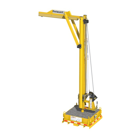
INstALLING tHe JIb boom oN tHe bAse: Refer to Figure 2 for identification of Jib Boom system components:
1.
INstALL stAtIoNAry bAse: Counterweight Bases (L. M) are supplied pre-assembled. See Step 3.2 regarding
Concrete Filled Bases.
2. AssembLe tHe uPrIGHt AssembLy: Assemble the Jib Boom as instructed in the Assembly Instruction
(see Table 1).
3. INstALL HItcH bALL Post: See Figure 7. Insert the Hitch Ball Post (A) in the sleeve in the Counterweight Base.
Tighten the Upright Assembly Locking Bolt (B) securely to prevent the Hitch Ball Post from rotating.
4. PosItIoN tHe uPrIGHt AssembLy over tHe bAse: Lift the assembled Upright Assembly by the Hoist Ring (C)
with a Forklift or Crane. Position the Upright Assembly so the Mounting Socket in the bottom of the Upright Assembly
is directly over the Hitch Ball Post.
5. Lower tHe uPrIGHt AssembLy oNto tHe bAse: Lower the Upright Assembly onto the Base until the Hitch Ball
fully seats in the Upright Assembly mounting socket.
6. rotAte ANd Lock tHe uPrIGHt AssembLy: Rotate the Upright Assembly to the desired position and then insert
the Rotation Lock Pin (D) to prevent the Upright Assembly from rotating during transport or use.
3.4
INstALL LeveLING JAcks: If included with your Jib Boom Assembly (see Table 1), install Leveling Jacks on the
Counterweight Base as instructed in the included Installation Instruction 5903386.
3.5
INstALL JIb rescue ANd retrIevAL kIt: If included with your Jib Boom Assembly (see Table 1), install the Jib
Rescue and Retrieval Kit as instructed in the included Capital Safety instruction 5903369.
3.6
trANsPortING tHe system: Figure 8 illustrates transport of the Jib Boom Assembly. Prepare and transport the
system as follows:
1. rotAte tHe uPrIGHt AssembLy: Remove the Rotation Lock Pin (A), rotate the Upright Assembly for best
clearance during transport, and then reinsert the Rotation Lock Pin to prevent the Upright Assembly from rotating
during transport.
2. trANsPort tHe system: Transport the Jib Boom system with Counterweight Base to the desired work location
with a Forklift or Pallet Jack and the Lifting Channels. Or, use a Crane or similar equipment and the Lifting Eyes on the
Counterweight Base. Transport the Upright Assembly from one base to another base with a Crane, Hoist or Forklift
with a Lifting Strap/Chain and the Hoist Ring (B) on the top end of the Upright Assembly.
CaUtIon:
Never transport the system without the Jib Boom fully lowered and the Rotation Lock Pin inserted.
WarnInG:
Do not transport at speeds exceeding 5 mph (8 kph). Never transport the system on slopes greater than 10°. Excessive
speeds or slopes may cause system and tow vehicle tip-overs resulting in serious injury or death.
WarnInG:
When transporting the Jib Boom, be aware of overhead obstructions and electrical hazards which may result in serious
injury or death.
1 Qualified Person:
A person with a recognized degree of professional certificate and with extensive knowledge, training, and experience in the fall protection
and rescue field who is capable of designing, analyzing, evaluating, and specifying fall protections and rescue systems to the extent required by OSHA and other
applicable standards
Jib Boom Assembly must be installed by a Qualified Person and the installation must be certified
®
9