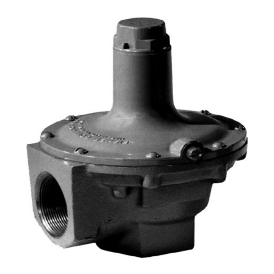
Emerson 289 Series Buku Petunjuk - Halaman 3
Jelajahi secara online atau unduh pdf Buku Petunjuk untuk Unit Kontrol Emerson 289 Series. Emerson 289 Series 11 halaman.

chemicals or other foreign materials. If piping is to
be attached to the valve outlet, the following parts
(if they are connected to the valve outlet as
shown in Figures 6 through 10) must first be
removed: the screen (key 9), the snap ring (key
13) and the gasket (key 15). A typical installation
of a 289 Series relief valve is shown in Figure 4.
Warning
!
If using a 289 Series relief valve on
hazardous or flammable gas service,
personal injury and property damage
could occur due to fire or explosion of
vented gas that may have accumulated.
To prevent such injury or damage, provide
piping or tubing to vent the gas to a safe,
well-ventilated area. Also, when venting a
hazardous gas, the piping or tubing should
be located far enough away from any
buildings or windows so to not create a
further hazard and the vent opening
should be protected against anything that
could clog it.
5. Apply pipe compound to the male pipeline threads
only; do not apply pipe compound to the internal
body threads. Then install the relief valve so that
the flow through it will match the direction arrow or
marking cast on the valve body.
When installing the molded diaphragm in the
289 Series Relief Valves, make sure the diaphragm
convolutions is installed in the down position as
shown in Figure 3.
Startup
Key numbers are shown in Figures 6 through 10.
With proper installation completed and system
equipment properly adjusted, close any vent valves
and slowly open the upstream shutoff valve while
using pressure gauges to monitor pressure.
Note
To ensure proper operation of the pitot
tube, if present, the spring case (key 2)
must be tightly sealed. It is recommended
that the gasket (key 15) be replaced
whenever the closing cap (key 14) is
removed. Antiseizing sealant should be
applied to the adjusting screw (key 6)
threads on valves without closing caps.
บริ ษ ั ท เอดี ด ี เฟอร์ เ นส จ ำกั ด
ADD FURNACE CO.,LTD.
44 ซอยบรมราชชนนี 70 ถนนบรมรำชชนนี แขวงศำลำธรรมสพน์ เขตทวี ว ั ฒ นำ กรุ ง เทพฯ 10170
โทร: 02-888-3472 โทร: ออกแบบ
08-08-170-170
:
https://www.add-furnace.com E-mail:
แฟกซ์ : 02-888-3258
M1048
INlet pressure
outlet pressure
Figure 2. 2 NPT Type 289H Operational Schematic
Figure 3. Installation of Diaphragm
Set point verification should be included in startup
procedures. If set pressure adjustment is necessary,
monitor the inlet pressure with a gauge during the
adjustment procedure. Remove the closing cap (key 14)
or loosen the hex nut (key 11) and turn the adjusting
screw (key 6) clockwise to increase or counterclockwise
to decrease the relief pressure setting.
289 Series
INSTALL
DIAPHRAGM
CONVOLUTION
DOWN
3
