Autonics MD5-HD14 Panduan Produk - Halaman 2
Jelajahi secara online atau unduh pdf Panduan Produk untuk Pengontrol Autonics MD5-HD14. Autonics MD5-HD14 3 halaman. Micro step 5-phase stepper motor driver
Juga untuk Autonics MD5-HD14: Manual (10 halaman)
• Re-supply power after 1 sec from disconnected power.
• Do not input CW, CCW signal at the same time in 2 pulse input method.
• When the signal input voltage is exceeded the rated voltage, connect additional resistance at
the outside.
• Set RUN current within the range of motor's rated current depending on the load.
When the rated motor current is exceeded, the heat may increased and motor may be
damaged.
• If the driver stops by the current down function, switches to STOP current.
If the current down function is not set or HOLD OFF signal is [H], STOP current switching will
not be executed.
• Use twisted pair (over 0.2 mm
) for the signal cable within 2 m.
2
• In case of extending the motor cable, use the cable that is thicker than lead cable.
• Keep the distance between power cable and signal cable over 10 cm.
• If the power is supplied while TEST switch is ON, the motor operates immediately and it may
be dangerous.
• Do not change any setting switches (function selection, RUN/STOP current, resolution) during
the operation or after supplying power.
Failure to follow this instruction may result in malfunction.
• Motor vibration and noise may occur in a specific frequency range.
- Change the motor installation method or attach the damper.
- Use the unit out of the corresponding frequency range due to changing motor RUN speed.
• Maintain and inspect regularly the following lists.
- Unwinding bolts and connection parts for the unit installation and load connection
- Abnormal sound from ball-bearing of the unit
- Damage and stress of lead cable of the unit
- Connection error with motor
- Inconsistency between the axis of motor output and the center, concentric (eccentric,
declination) of the load, etc.
• This product does not contain a protection function for a motor unit.
• This unit may be used in the following environments.
- Indoors (in the environment condition rated in 'Specifications')
- Altitude max. 2,000 m
- Pollution degree 2
- Installation category II
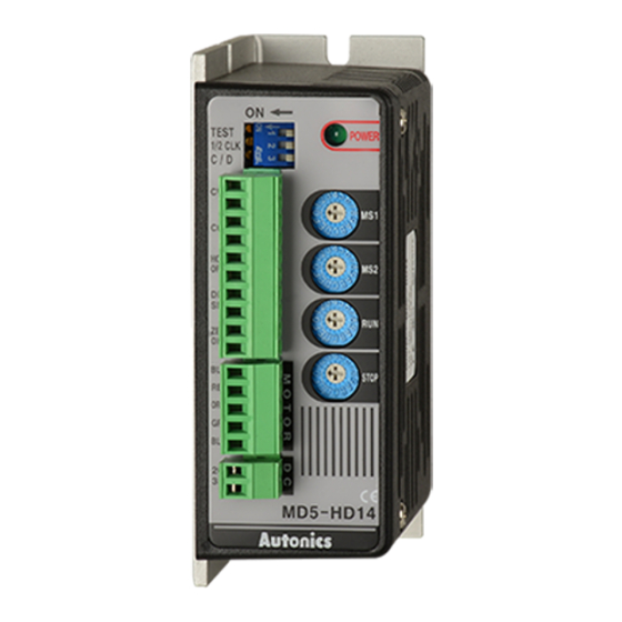
Product Components
• Product
Dimensions
• Unit: mm, For the detailed drawings, follow the Autonics website.
4.5
20
39.5
Specifications
Model
MD5-HD14
Power supply
24 - 35 VDCᜡ ± 10%
01)
Max. current
3 A (based on ambient temp. 25℃, ambient humi. 55%RH)
consumption
RUN current
0.4 - 1.4 A / Phase
02)
Stop current
27 to 90% of RUN current (set by STOP current setting rotary switch)
RUN method
Bipolar constant current pentagon drive
Basic step angle
0.72° / Step
1, 2, 4, 5, 8, 10, 16, 20, 25, 40, 50, 80, 100, 125, 200, 250 division
Resolution
(0.72° to 0.00288° / Step)
Pulse width
≥ 10 μs (CW / CCW), ≥ 1 ms (HOLD OFF)
Duty rate
50% (CW / CCW)
Rise, Fall time
≤ 130 ns (CW / CCW)
Pulse input voltage [H]: 4 - 8 VDCᜡ, [L]: 0 - 0.5 VDCᜡ
7.5 - 14 mA (CW / CCW), 10 - 16 mA (HOLD OFF, DIVISION SELECTION, ZERO
Pulse input current
OUT)
Max. input pulse freq. ≤ 500 kHz (CW / CCW)
Input resistance
270 Ω (CW / CCW), 390 Ω (HOLD OFF, DIVISION SELECTION), 10 Ω (ZERO OUT)
Insulation resistance Between all terminal and case: ≥ 100 MΩ (500 VDCᜡ megger)
Dielectric strength Between all terminal and case: 1,000 VACᜠ 50 / 60 Hz for 1 minute
± 500 VDCᜡ square wave noise (pulse width: 1 ㎲) by the noise simulator
Noise immunity
1.5 mm double amplitude at frequency 5 to 60 Hz (for 1 minute) in each X,
Vibration
Y, Z direction for 2 hours
Vibration
1.5 mm double amplitude at frequency 5 to 60 Hz (for 1 minute) in each X,
(malfunction)
Y, Z direction for 10 minutes
Ambient temp.
0 to 40℃, storage: -10 to 60℃ (no freezing or condensation)
Ambient humi.
35 to 85% RH, storage: 35 to 85% RH (no freezing or condensation)
Approval
ᜢ ᜫ
Unit weight
≈ 220 g (≈ 327.5 g)
(packaged)
01) If a power supply is over 30 VDCᜡ, the torque characteristics in the high speed range will improve, but the
driver's temperature will increase as well. Install the unit in well-ventilated area. The torque may vary depending
on power supply.
02) RUN current varies depending on the RUN frequency, and the max. instantaneous RUN current varies depending
on load.
• Instruction manual
86
76.5
74
38
4.5
Function Setting
■ Function selection DIP switch
No.
Name
Function
Description
[ON: 250 pps rotation, OFF: Disable]
It rotates 30 rpm in full step, rotation speed may vary
according to resolution setting.
Self diagnosis
1
TEST
Rotation speed =
function
In 1 pulse input method, it rotates to CCW and in 2 pulse
input method, it rotates to CW.
The setting must be changed when the motor stops.
[ON: 1 pulse input method, OFF: 2 pulse input method]
1 pulse input method:
CW → Operating rotation signal input
Pulse input
CCW → Rotation direction signal input
2
1/2 CLK
method
([H]: Forward rotation, [L]: Reverse rotation)
2 pulse input method:
CW → Forward rotation signal input
CCW → Reverse rotation signal input
[ON: Disable, OFF: Enable]
This function allows to reduce the current provided to
Auto current
motor automatically for preventing severe motor heat
3
C/D
down
while motor stops.
If motor RUN pulse is not applied, the current provided to
motor reduces as set STOP current.
■ RUN current
0
1
2
3
Setting
Current
0.4 0.5 0.570.630.710.770.84 0.9 0.961.021.091.151.221.271.33 1.4
(A / Phase)
• It is able to set the RUN current of the motor.
• When RUN current is increased, RUN torque of the motor is also increased.
• When RUN current is increased, the heat of the motor is also increased.
• Set RUN current for the load within range of the rated current of the motor.
• The setting must be changed when the motor stops.
■ Stop current
Setting
0
1
2
3
%
27 31 36 40 45 50 54 58 62 66 70 74 78 82 86 90
• This function allows to control the current provided to motor for preventing severe motor
heat while motor stops.
• The setting is applied when using C/D (Current Down) function.
• STOP current setting value is % ratio of set RUN current.
E.g.) If the RUN current is 1.4 A, STOP current setting is 40%, the STOP current is 1.4 A×0.4 = 0.56 A.
• When STOP current is increased, RUN torque of the motor is also increased.
• When RUN current is increased, the heat of the motor is also increased.
• The setting must be changed when the motor stops.
■ Micro step setting (Micro step: Resolution)
Setting
0
1
2
3
Resolution
1
2
4
5
Step angle (°) 0.72 0.36 0.18 0.144 0.09 0.072 0.045 0.036 0.0288 0.018 0.0144 0.009 0.0072 0.00576 0.0036 0.00288
• Two resolutions can be set with MS1, MS2 switch.
• MS1 or MS1 can be selected with DIVISION SELECTION signal. ([L]: MS1, [H]: MS2)
• It sets the step angle (rotation angle for 1 pulse).
• The set step angle is divided angle with set revolution by setting basic step angle of 0.72
• The set step angle is the angle divided by the set resolution of 0.72° basic step angle of
5-phase stepper motor.
• The divided step angle is based on following equation.
Basic step angle (0.72°)
Set step angle =
Resolution
• In case of using built-in gear motor, the step angle is applied the angle divided by reduction ratio.
Step angle
= Step angle applied by gear
Gear ratio
0.72°
E.g.)
= 0.072°
10 (1:10)
• The setting must be changed when the motor stops.
■ Zero point excitation output signal (ZERO OUT)
ON
CW Pulse
OFF
ON
CCW Pulse
OFF
ON
ZERO OUT
OFF
0
1
2
3
4
• This output indicates the beginning of the stepper motor excitation sequence, and allows to
know the rotational position of the motor shaft.
• Regardless of the resolution, th pulse is output every 7.2° rotation of motor shaft. (50 outputs
per motor rotation)
E.g.) Full step: 1 output for 10 input pulse, 20 division: 1 output for 200 input pulse
■ HOLD OFF
• This signal is for rotating motor shaft with external force or manual positioning.
- When HOLD OFF signal remains over 1 ms as [H], motor excitation is released.
- When HOLD OFF signal remains over 1 ms as [L], motor excitation is in normal status.
• Refer to 'I/O Circuit and Connections'.
• The setting must be changed when the motor stops.
30 rpm
Resolution
4
5
6
7
8
9
A
B
C
4
5
6
7
8
9
A
B
C
4
5
6
7
8
9
A
B
C
8
10 16 20 25 40 50 80 100 125 200 250
5
6
7
8
9
0
1
D
E
F
D
E
F
D
E
F
1
0