Autonics PA10-V Panduan Memulai Cepat - Halaman 3
Jelajahi secara online atau unduh pdf Panduan Memulai Cepat untuk Pengontrol Autonics PA10-V. Autonics PA10-V 8 halaman. Multifunctional sensor controller
Juga untuk Autonics PA10-V: Buku Petunjuk (2 halaman)
PA10 Series
Function Diagram
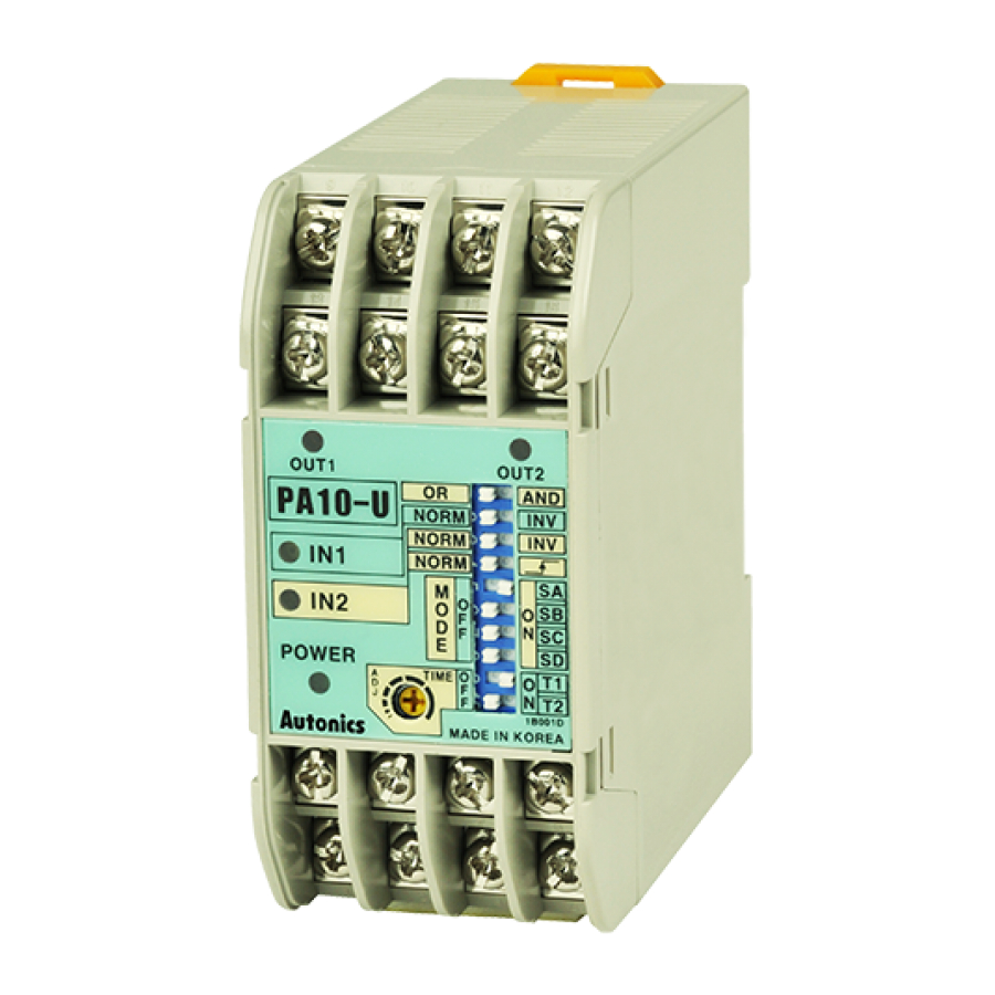
●PA10-U
+5V
IN1
IN1 input indicator
+5V
IN2
IN2 input indicator
●PA10-V ●PA10-VP
+12v
IN1
+12v
IN2
IN2 input indicator
※ Add when it is PNP input
Front Panel Identification
● PA10-U
1. Power indicator:
LED is turned on when AC power applied
2. Output1 indicator:
Indication of output 1 operation status
3. Output2 indicator:
Indication of output 2 operation status
4. Sensor input indicator
Indicates sensor input signal
(LED is turned on when sensor input is Low)
5. AND/OR selection switch:
Select "AND" or "OR" for IN1, IN2 Input
6. Selection switch of sensor input signal
(Reverse function of input signal)
● NORM:LED is turned on when input signal is low. (
● INV:LED is turned on when input signal is high. (
7. Derivative action selection of IN2 input signal
(OR/AND selection switch: AND)
(When input signal is high (
● NORM: IN2 input signal is operating as reverse turn function
: IN2 Derivative action of IN2 input signal. ( ※ Refer to O-7,
●
● PA10-V/PA10-VP
5
1. Power indicator:
2. Output indicator:
3. Sensor input indicator:
3
2
4
4. Selection switch of sensor input signal
1
Power
Power
5. Terminal block
※ When IN1, IN2 input signal is AND, OUT will work.
O-4
NORM
AND
INV
NORM
OR
INV
IN1 input indicator
NORM
INV
NORM
INV
OUT output indicator
)
) it is effective signal.)
LED is turned on when AC power applied
Indicates output operation
● PA10-V: Indicates sensor input signal
(LED turns on when sensor input is Low)
● PA10-VP: Indicates sensor input signal
(LED turns on when sensor input is
High)
● NORM: When sensor input signal is Low,
it is vaild signal.
● INV: When sensor input signal is High, it
is valid signal.
Control
NORM
box
MODE
(Derivative)
SW
● PA10-W ● PA10-WP
+12v
OUT
IN1
O·C
OUT
IN2
※ Add when it is PNP input
11
3
2
5
6
4
7
8
1
9
10
Power
)
Power
Applicatio of derivative operation,)
● PA10-W/PA10-WP
6
2
4
1
Power
Power
※ IN1, IN2 operates
individually.
OUT1 output indicator
O·C
OUT1
O·C
OUT2
OUT2 output indicator
IN1 input indicator
+12v
OUT1 output
NORM
indicator
+12v
INV
NORM
INV
IN2 input indicator
OUT2 output indicator
8. Selection switch for operation mode:
See < Operation mode> in next page.
9. Selection switch of time range and max. input
frequency: It is the switch to select time range (1
to 7 mode) or allowable input frequency (9 to 11
mode).
● Time range: Approx. 0.01 to 0.1sec.
Max. input frequency: 100kHz
● Time range: Approx. 0.1 to 1sec.
Max. input frequency: 10kHz
● Time range: Approx. 1 to 10sec.
Max. input frequency: 1kHz
● Time range: Approx. 10 to 100sec.
Max. input frequency: 100Hz
10. Timer adjuster
Adjust time as same as the range of 9.
11. Terminal block
1. Power indicator:
LED is turned on when AC power applied
2. Output1 indicator:
Indication of output 1 operation status
3. Output2 indicator:
Indication of output 2 operation status
4. Sensor input indicator:
3
●PA10-W: lndicates sensor input signal
(LED is turned on when sensor input is
5
Low)
●PA10-WP: Indicates sensor input signal
(LED is turned on when sensor input is
High)
5. Selection switch of sensor input signal
●NORM: When sensor input signal is Low,
it is valid signal.
●INV: When sensor input signal is High, it
is vaild signal.
6. Terminal block
+12v
OUT
+12v
OUT1
+12v
OUT2