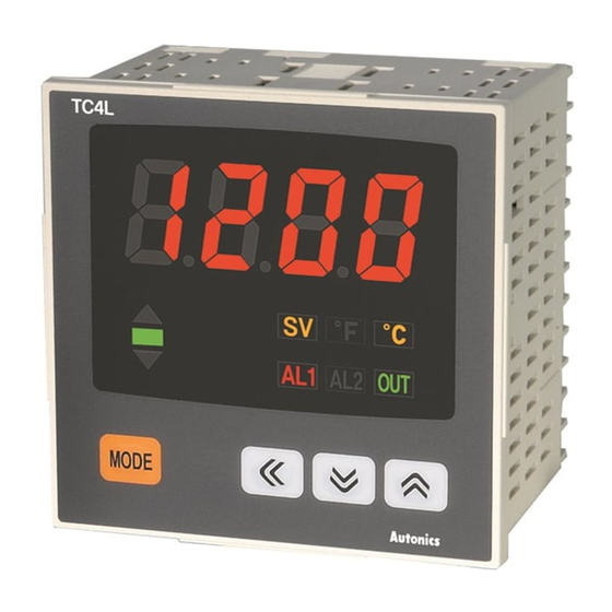
Autonics TC4L Manual - Halaman 6
Jelajahi secara online atau unduh pdf Manual untuk Pengontrol Suhu Autonics TC4L. Autonics TC4L 14 halaman. Touch switch type temperature controller
Juga untuk Autonics TC4L: Manual (14 halaman), Manual (2 halaman), Buku Petunjuk (2 halaman), Panduan Memulai Cepat (9 halaman), Panduan Memulai Cepat (10 halaman)

Parameter Group
①
Press any key among
,
,
,
SV setting
※ 1: It is not displayed for AC/DC power model (TC4 - 2R).
※ If no key entered for 30 sec., it returns to RUN mode automatically and the set value of
parameter is not be saved.
※
This parameter might not be displayed depending on other parameter settings.
① Press any key once in RUN mode, it advances to set value setting group.
② Press
key over 2sec. in RUN mode, it advances to parameter group 1.
③ Press
key over 4sec. in RUN mode, it advances to parameter group 2.
④ First parameter will be displayed on viewer when it advances to the setting group.
⑤ Press
key over 3sec. in the setting group, it returns to RUN mode.
※ Exception: Press
key once in SV setting group it returns to RUN mode.
※ Press
key again within a sec after return to RUN mode by press
3sec., it advances to the first parameter of previous setting group.
※ Parameter setup
Parameter group 2 → Parameter group 1 →
• Set parameter as the above considering parameter relation of each setting group.
• Check parameter set value after change parameter of setting group 2.
※ Indicator model (TC4 -N N)displays shaded parameter (
※Alarmoperationmode[ AL-1 , AL-2 ] parameter of parameter group 2 is decided whether to display according by alarm output type.
※ If alarm operation mode [ AL-1 , AL-2 ] of parameter group 2 is set to AM)_ / SBa
Run mode
②
2 sec.
Parameter group 1
PAR1
[
3 sec.
④
AL1
AL1 alarm temperature
AL2
AL2 alarm temperature
AT
Auto tuning
P
Proportional band
I
Integral time
D
Derivative time
Manual reset
RSET
(Normal deviation correction)
HYS
ON/OFF control hysteresis
SV setting
) of parameter group 2.
Economical PID Control
Parameter 2group
]
IN-T
Input type
UNIT
Temperature unit
IN-B
Input correction
MAvF
Input digital filter
L-SV
SV low-limit value
H-SV
SV high-limit value
O-FT
Control output operation
C-MD
Control type
OUT
Control output
SSrM
SSR drive output method
T
Control cycle
AL-1
AL1 alarm operation mode
AL-2
AL2 alarm operation mode
AHYS
Alarm output hysteresis
LBaT
LBA monitoring time
LBaB
LBA detection range
DI-K
Digital input key
Control output MV in case of
ErMV
input break error
key over
LOC
Parameter lock
/ LBa , AHYS parameter is not displayed.
⑤
③
4 sec.
PAR2
[
]
3 sec.
※1
H-59
(A)
Photoelectric
Sensors
(B)
Fiber
Optic
Sensors
(C)
Door/Area
Sensors
(D)
Proximity
Sensors
(E)
Pressure
Sensors
(F)
Rotary
Encoders
(G)
Connectors/
Sockets
(H)
Temperature
Controllers
(I)
SSRs / Power
Controllers
(J)
Counters
(K)
Timers
(L)
Panel
Meters
(M)
Tacho /
Speed / Pulse
Meters
(N)
Display
Units
(O)
Sensor
Controllers
(P)
Switching
Mode Power
Supplies
(Q)
Stepper Motors
& Drivers
& Controllers
(R)
Graphic/
Logic
Panels
(S)
Field
Network
Devices
(T)
Software
