Galaxy DX 949 Panduan Pemilik - Halaman 5
Jelajahi secara online atau unduh pdf Panduan Pemilik untuk Transceiver Galaxy DX 949. Galaxy DX 949 12 halaman. Solid state citizens band am/ssb mobile transceiver
OPERATION
CONTROL FUNCTIONS
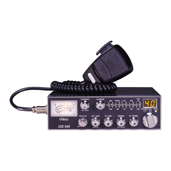
FRONT PANEL
1. ON/OFF VOLUME CONTROL : Turn clockwise to apply power to
the radio and to set the desired listening level.
2. SQUELCH CONTROL : This control is used to control or eliminate
receiver background noise in the absence of an incoming signal. For
maximum receiver sensitivity, it is desired that the control be adjusted
only to the point where the receiver background noise is eliminated. Turn
fully counter-clockwise, then slowly clockwise until the receiver noise
disappears. Any signal to be received must now be slightly stronger than
the average received noise. Further clockwise rotation will increase the
threshold level which a signal must overcome in order to be heard. Only
strong signals will be heard at maximum clockwise setting.
3. MIC GAIN/R.B. : Adjusts the microphone gain in the transmit and PA
modes. This controls the gain to the extent that full talk power is
available several inches away from the microphone. In the PUBLIC
ADDRESS (PA) mode, the control functions as the volume control.
Pushing this knob turns the Roger Beep on and off. When the Roger
Beep is on, the radio transmits an audio tone at the end of your
transmission. This indicates the end of your transmission so that people
who are having trouble hearing you will know that you are done
speaking. As a courtesy to others, use the Roger Beep only when
necessary.
- 7 -
4. RF GAIN CONTROL : This control is used to reduce the gain of the
receive amplifier under strong signal conditions.
5. DIMMER CONTROL : This knob controls the level of brightness for
the meter lamp and the channel display. Also, pushing this knob turns the
meter lamp and the display LED's on and off.
6. RF POWER CONTROL : This control allows the user to adjust RF
power output.
7. CHANNEL SELECTOR : This control is used to select a desired
transmit and receive channel.
8. FRONT PANEL METER : The Front Panel Meter allows the user to
monitor signal strength, RF output power, SWR level and the AM
Modulation level.
9. TALKBACK CONTROL : Pushing this knob turns the Talkback
circuit on and off. Adjust this knob for desired volume of Talkback. This
is used to monitor your own voice. For example, you could use this
feature to compare different microphones.
10. CLARIFIER : Allows tuning of the receive frequency above or below
the channel frequency by up to 1.0 KHz. Although this control is
intended primarily to tune in SSB signals, it may be used to optimize
AM signals.
11. SWR/MOD/PWR SWITCH : This switch controls the function of the
meter during the transmit mode. In the "SWR" position, the meter
indicates the Standing Wave Ratio (SWR) of your antenna. There are no
adjustments because the SWR circuit in this radio calibrates itself
automatically. When the switch is in the "MOD" position, the green scale
on the meter indicates your percentage of modulation. This operates in
AM only, not in SSB. When this switch is in "PWR" position, the meter
indicates your power output.
12. NB/ANL/OFF SWITCH : In the "ANL" position, the Automatic Noise
Limiter is activated. In the "NB/ANL" position, the Noise Blanker is also
activated. The Noise Blanker is very effective in eliminating repetitive
impulse noise such as ignition interference.
- 8 -