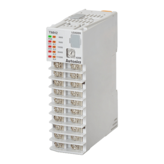
Autonics TMH Series Panduan Memulai Cepat - Halaman 6
Jelajahi secara online atau unduh pdf Panduan Memulai Cepat untuk Pengontrol Suhu Autonics TMH Series. Autonics TMH Series 6 halaman. Modular2/4-channel pid temperature controllers with screw connector

- Communication module: TMHC-22LE [Ladderless communication]
Status
Initial power ON
Indicator
PWR
Flash (4,800 bps)
LED 1 LED 2
(red)
Flash (9,600 bps)
(red)
Flash (19,200 bps)
(red)
Flash (38,400 bps)
(red)
Flash (115,200 bps)
(yellow)
Flash (4,800 bps)
(yellow)
Flash (9,600 bps)
(yellow)
Flash (19,200 bps)
(yellow)
Flash (38,400 bps)
(yellow)
Flash (115,200 bps)
- Communication module: TMHC-22EE [Ethernet communication]
Status
Initial power ON
Indicator
PWR (green) ON
LED 1 LED 2
(red)
-
(red)
-
(red)
-
(red)
-
(yellow)
-
(yellow)
(yellow)
Sequence-flashing
vertically for 5 sec
(yellow)
(yellow)
01) At the moment when power is on, the indicator of set communication speed flashes for 5 sec.
02) Indicator of the channel, which is in the process of auto-tuning, flashes at 1 sec interval.
03) When communicating with external device, PWR indicator flashes.
04) Turns on, when CH1 outputs cooling control in the heating&cooling control method.
05) Turns on, when CH2 outputs cooling control in the heating&cooling control method.
06) • ON: Internal comm. (normal) • Flash: Internal comm. (abnormal) • OFF: not communicating
07) • 1 sec interval flash: external comm. (normal) • ON: Internal comm. (normal) • Flash: Internal comm. (abnormal)
• OFF: not Internal communicating
08) The indicator corresponding to the certain setting value of CT input flashes according to the parameter.
• LED 1: CT Input Value Indication Lamp1 • LED 2: CT Input Value Indication Lamp2
09) At the moment when power is ON, the indicator of communication speed flashes for 5 sec at 1 sec interval.
• LED 1: HOST 1 • LED 2: HOST 2
3. PC loader port
PC loader port supports serial communication between single module and PC. It needs
communication converter for communicating.
4. Communication address setting switch (SW1)
Set the communication address. If changing the communication address by setting
switch, use the flat head driver which is 2mm size or plastic driver. If not, it may cause
product damage.
5. Rail lock
Rail lock helps installing the device. Refer to 'Installation Method' for the details.
6. Lock lever
Lock lever holds module body and base tightly.
7. Module lock connector hole
When connecting modules, insert module lock connector in the hole in order to enhance
coherence between them.
8. END Cover
When connecting modules, remove END cover in order to connect expansion connector.
9. CT input Terminal [Control module]
Refer to 'Connection' for the details.
9. Communication mode switch (SW2) [Ladderless communication module]
Select communication mode between RS485 and RS422.
10. Communication address group switch (SW2) [Control module]
When setting the communication address over 16, select +16.
11. Power / Communication terminal [Control basic module]
Supplies power to both basic control/expansion module and communicates with one or
more module.
Internal
Ladderless
Connection
09)
comm.
communication
Flash (red, read
Flash (green)
operation)
Flash (TMH2/4)
-
-
Flash (TMHA)
-
Flash (TMHE)
-
Flash (TMHCT)
-
Flash (send
ON
operation)
ON (TMH2/4) -
-
ON (TMHA)
-
ON (TMHE)
-
ON (TMHCT) -
Internal comm.
Connection
Flash (external device)
Flash (TMH2/4)
Flash (TMHA)
-
Flash (TMHE)
Flash (TMHCT)
ON
Flash (Ethernet comm.)
-
ON (TMH2/4)
-
ON (TMHA)
-
ON (TMHE)
-
ON (TMHCT)
Configuration Example
TMH2/4 expansion module, TMHA, TMHE and TMHCT are should be used with TMH2/4
basic module.
Each module is available to monitoring at DAQMatser via PC loader.
• Internal comm.: Receiving/Sending data between TMH2/4 and TMHA/E/CT
• External comm.: Communication with master for controlling
■ Control module: TMH2/4, Option module: TMHA/E/CT
inter-working
Max. 16 unit
Series (address range)
TMH2/4 (1 to 32)
● ● ●
External
comm.
Master
Basic module Expansion module
■ Communication module: TMHC
Ladderless communication
TMHC
(1 to 16)
Control module internal comm.
Port 1
COM 1
Comm. module internal comm.
Master
Port 2
COM 2
TMHC
Control module internal comm.
Comm. module internal comm.
Max connection per 1 group TMHC 4 units
TMHC
Control module internal comm.
COM 1
Comm. module internal comm.
Max. connection:
4 groups
TMHC
Control module internal comm.
Comm. module internal comm.
Max connection per 1 group TMHC 4 units
Ethernet communication
TMHC
(1 to 16)
Control module internal comm.
COM 1
Comm.module internal comm.
Master
COM 2
TMHC
Control module internal comm.
Comm. module internal comm.
Max. connection: TMHC 16 units
18, Bansong-ro 513Beon-gil, Haeundae-gu, Busan, Republic of Korea, 48002
www.autonics.com | +82-2-2048-1577 | [email protected]
Max. 32 unit
Max. 16 unit
TMHA (33 to 48)
TMHE (49 to 64)
TMHCT (65 to 80)
● ● ●
● ● ●
Internal
comm.
Terminal resistance
Group 1
TMH2/4
TMHA/E/CT
(17 to 32)
(33 to 80)
● ● ●
● ● ●
Max. 16 unit
Max. 16 unit
TMH2/4
TMHA/E/CT
● ● ●
● ● ●
Group 2
TMH2/4
TMHA/E/CT
● ● ●
● ● ●
TMH2/4
TMHA/E/CT
● ● ●
● ● ●
TMH2/4
TMHA/E/CT
(17 to 32)
(33 to 80)
● ● ●
● ● ●
Max. 16 unit
Max. 16 unit
TMH2/4
TMHA/E/CT
● ● ●
● ● ●
-
● ● ●
