Emerson 3200 Petunjuk Pemasangan, Pengoperasian, dan Pemeliharaan - Halaman 5
Jelajahi secara online atau unduh pdf Petunjuk Pemasangan, Pengoperasian, dan Pemeliharaan untuk Alat Ukur Emerson 3200. Emerson 3200 15 halaman. Electronic water level gauge
Juga untuk Emerson 3200: Panduan Pengguna (20 halaman)

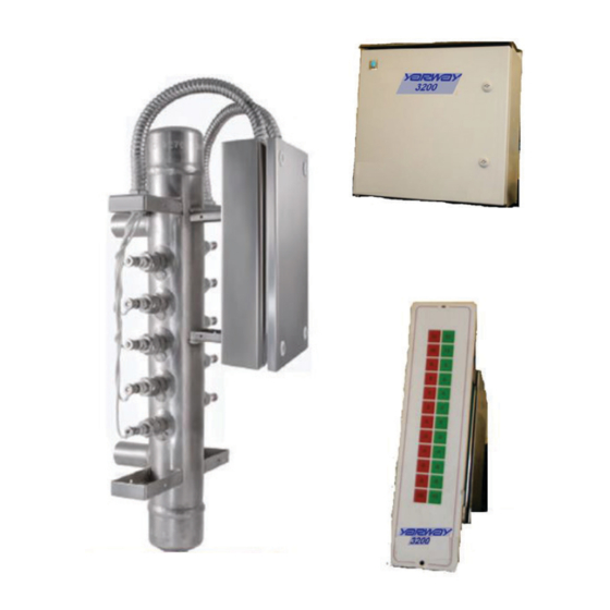
YARWAY 3200 ELECTRONIC WATER LEVEL GAUGE
INSTALLATION, OPERATION AND MAINTENANCE INSTRUCTIONS
4.4.3 Protective Ground Wiring
Locate the Protective Ground post inside the
enclosure beside the ground symbol. This post
will be close to the power supply terminals.
A green/yellow wire, having minimum AWG size
as the supply cable, and fitted with a ring type
connector is to be secured to the ground post
as shown in Figure 5.
Ensure placement of the ground ring connector
is between the two washers.
4.4.4 At the Remote Display Panel
The display panel insert is connected to the
Detection and Verification Cubicle by a 16 to
18 AWG multi conductor cable. Shielding is
required if electrical conductors other than
those for the Yarway low voltage display share
the same wiring conduit.
When several display panels are connected
to a single electronic module, each panel
can be connected to either the Electronic
Module terminal strip or the terminal strip of a
preceding display panel. Care must be taken to
match the corresponding terminal connections.
Light Emitting Diodes (LEDs) are used on the
display panel. These LEDs have an expected 30-
year life and can be replaced only on a modular
basis.
4.5 Control Outputs (See Figure 8)
4.5.1 Detection Outputs
The control output from each channel is
a Form-C type contact. These outputs are
designated Relays "1" through "12", for
channels 1 to 12, respectively.
These contacts are not fused. Exceeding the
rating will shorten the output relays life. Also,
incorrect wiring may cause a short circuit and
destroy the relay and/or circuit board.
Careful consideration should be given to the
design of the alarm and trip logic. Power loss
or vessel blowdown could inadvertently shut
down the steam generator or leave the unit
without protection.
These contacts can be wired to remote
indicators and control circuits as required.
4.5.2 Electronics Fault Output
A Form-C type relay contact is provided to allow
external monitoring of the operation of the
Yarway 3200. This relay is normally energized.
Loss of power to the unit or detection of an
internal fault condition will cause the relay to
de-energize, opening the contacts. The fault
detection circuit covers clock failure, continuity
failure and two internal power supplies.
4.5.3 Level Fault Output
The Yarway 3200 is also equipped with a Level
Fault relay. This relay is normally de-energized
and has a Form-C type output contact
(normally open relay contact).
See Section 4.5 for the explanation of this
circuit.
FIGURE 4
Ground Symbol
FIGURE 5
Ground Hardware
5
