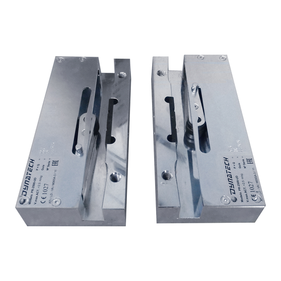
Dynatech PQ-4000 UD Petunjuk Penggunaan dan Pemeliharaan Manual - Halaman 11
Jelajahi secara online atau unduh pdf Petunjuk Penggunaan dan Pemeliharaan Manual untuk Peralatan Keselamatan Dynatech PQ-4000 UD. Dynatech PQ-4000 UD 19 halaman. Progressive safety gear
Juga untuk Dynatech PQ-4000 UD: Petunjuk Penggunaan Manual (11 halaman)

INSTRUCTIONS: PQ-4000-UD
Date: 20/10/2020
Revision: 08
Lower limit
2100
P+Q (Kg)
2173
Upper limit
2335
Loads may be duplicated through configuration of this tandem safety gear. See Manual DYN 37/8 – Extendible
T25UD/T25 Tandem safety gear for further information.
3 INSTALLATION AND ADJUSTMENT
3.1 ASSEMBLY ON THE FRAME
The holes should be made on the frame's uprights to secure the safety gear, according to the dimensions and
position displayed in the safety gear drawings attached (DYN 11.C001.01), ensuring that the guide rail's axis
is centred with the frame.
To secure the safety gear onto the frame, we recommend a 79.09 Nm tightening torque for grade 8.8 M12
bolts, and of 111 Nm for grade 10.9 bolts.
Figure 2: Assembling the safety gear onto the
frame (1)
�
�
�
Safety gear position:
a) The safety gears should be assembled in the position displayed in Figure 4
b) The roller for upwards jamming is indicated with letter "A". That is to say, roller "A" should be on the
upper part of the safety gear.
c) The roller for downwards jamming is indicated with letter "D". That is to say, roller "D" should be on
the lower part of the safety gear.
Cod: DYN 11.01.08
2222
2411
2402
2606
2582
2801
Figure 3: Assembling the safety gear onto the frame (2)
2610
2851
3095
2821
3081
3345
3032
3312
3595
3351
3722
3622
4023
3893
4324
4
