Galletti DST 56 Manual Teknis dan Instalasi - Halaman 6
Jelajahi secara online atau unduh pdf Manual Teknis dan Instalasi untuk Kipas angin Galletti DST 56. Galletti DST 56 8 halaman. Air destratifiers
Juga untuk Galletti DST 56: Manual Teknis dan Instalasi (8 halaman)
DST
9
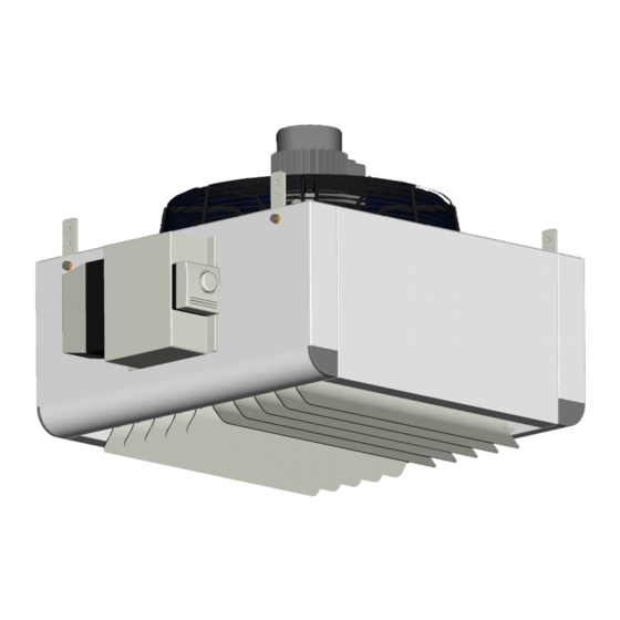
INSTALLATION
When choosing an installation site, you should observe the following rules:
- do not install the unit in places where inflammable gases are present;
- do not expose the unit directly to sprays of water;
- install the unit on walls or ceilings able to withstand its weight; use
accessories suited to the purpose and suitable screw anchors.
Store the unit in its packing container until you are ready to install it to prevent
dust from infiltrating inside it.
Installation, maintenance and cleaning jobs may be carried out only with
the power supply disconnected.
Do not modify the indoor electrical connections and the components of the
unit.
Set the working temperature on the thermostat before lifting the unit.
Using suitable lifting equipment (a forklift truck is recommended), convey the
unit to the installation site and rest it on the floor with the fins facing down.
Use the suspending brackets on the back of the cabinet to support the
destratifier; before securing the unit to the ceiling ensure that the supporting
chains, the studs and the surface used are able to support it.
Maintain adequate space around the destratifier to allow it to operate
correctly and to allow routine and reactive maintenance to be performed.
When the installation has been finished, check the chains fastening to the
ceiling, check that the electrical wiring have been thightened, open the
deflecting baffles and connect the unit to power supply in order to check its
operation.
Make the electrical connections with the power supply disconnected, in
accordance with current safety regulations. All the wiring must be done by
qualified personnel.
Scrupulously follow the wiring diagram provided.
Check that the mains electricity supply is compatible with the voltage shown
on the unit rating plate.
Each unit requires a switch (IL) on the feeder line with a distance of at
least 3 mm between the opening contacts, and a suitable safety fuse
(FL).
R
400/3/50
S
T
IL
Line circuit-breaker (NOT SUPPLIED)
FL
Protection fuse (NOT SUPPLIED)
ISM
Overload cut-out
K1
remote control switch
T
Thermostat
M
Motor
AP66000443 - 02
WIRING DIAGRAM
FL
1
2
3
4
5
6
6
All copying, even partial, of this manual is strictly forbidden
1
1 3 5
13
A1
K1
A2
2
4
6
14
1
3
5
ISM
2 4
6
11
M
M1
3~
12
1
K1
T
4
4
4