Hiking DTS238-7 Manual - Halaman 3
Jelajahi secara online atau unduh pdf Manual untuk Alat Ukur Hiking DTS238-7. Hiking DTS238-7 15 halaman. Din rail , 3 phase wifi smart energy meter
Under the rated voltage , rated frequency and COS=1 , the meter shall start and continue to register on
application of 0.2% In (if CT is used) or 0.4% Ib .
2.2.4Anti-creeping
The meter has anti-creeping logical circuit. When 115%Un is connected to the meter and current circuit is cut
, the meter shall not create more than one pulse in a stipulated time
2.2.5 Average-life
The meter can be used for at least 10 years in normal operation specified in this manual
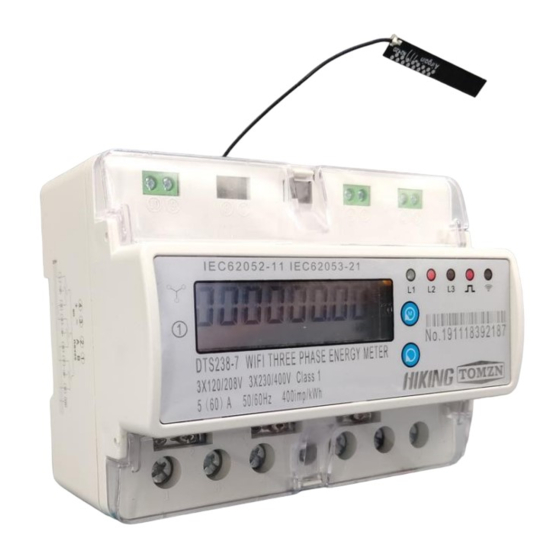
2.2.6LCD: 6+2 (999999.99kWh)
3.Basic Features
3.1 Measuring positive & negative active energy with negative energy accumulated into positive energy,.
3.2The meter also display three phase real voltage , real current , real active power , real power factor , real
frequency
3.3 Pulse LED indicates working of meter,Pulse output with optical coupling isolation
3.4 RS485 communication port and WIFI communication
3.5 Measuring active energy without calibration under long term operation
3.6 display step by step with button
3.7 it can use APP software for data reading and remoter control on/off.
3.8 it has overvoltage and undervoltage protection , it can set value from APP
3.9 it has overload protection ,it can set value from APP
3.10 it has timing control function , it can set value from APP
3.11 it can reset the active energy to zero from APP
4.Working principles
Three phase voltage and current are sampled from respective sampling circuit and transformed into suitable
signal, which is carried into integrated circuit , then the meter output pulse signal in positive appropriation to
measured power to drive step-motor counter or LCD counter to realize energy measurement. The meter has
energy pulse output for testing with pulse width of 80+20ms
Diagram for Working Principles
5. Structure
The meter consists of meter base , meter cover , terminal base , terminal cover . there are lead seal on
meter cover and terminal cover . A special screw is used to fix the terminal cover on which a lead seal can be
installed
6. Usage
6.1 schematic diagram