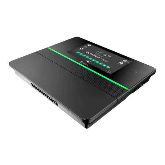
Adesys Octalarm-Touch Panduan Memulai Cepat - Halaman 4
Jelajahi secara online atau unduh pdf Panduan Memulai Cepat untuk Panel sentuh Adesys Octalarm-Touch. Adesys Octalarm-Touch 6 halaman.
Juga untuk Adesys Octalarm-Touch: Panduan Memulai Cepat (6 halaman)

3.
More system features
3.1.
Screen
Scherm pictogrammen
1
RFID reader
2
Brand logo
The screen is made of glass with a touchscreen in the middle as seen
in the picture above. Do not use hard objects on the touchscreen
as these will leave scratch marks and potentially couse it to become
inoperable.
To use RFID, place an RFID tag within 10 mm of the RFID reader.
3.2.
Power
Placing the power cable in the S-shaped holder creates a strain relief.
When replacing or using a power supply cord not included by Adésys
the power supply cord must comply with IEC 60227-1.
3.3.
Battery
Battery compartiment
1
Velcro fastener
2
Battery connector location
3
Battery label
Batterij label (Europe)
Place the battery on the battery flat and secure it tightly with
Velcro. Then connect the connector.
Caution:
Only use the battery for the Octalarm-Touch Pro (S-Batt-
6.4V) supplied by Adésys. This battery has been developed by
Adésys and has been fully tested. (Replacing the battery with an
incorrect type may cause damage to the device and the battery.)
3.4.
PSTN configuration
There are 2 ways to connect the Octalarm-Touch Pro to the
PSTN:
•
standalone;
•
Additional telephone
devices on the same
PSTN line (Fax /
Central Office etc.).
The PSTN line can
be connected to the
Octalarm-Touch Pro's RJ11 "Line In" connector. In case additional
devices need to be connected to the same PSTN line, it is very
important that no other device can occupy this line, when the
Octalarm-Touch Pro has to call out an alarm message. By doing
so no other device can interfere with the alarm device.
When an alarm message has to be sent out, all other PSTN
devices are automatically disconnected from the PSTN line by
means of a "Line-Seize" relay.
Caution:
Users must check that the "Line Size" feature is working properly
immediately after installation and repeat this check frequently.
This is necessary in order to ensure that the device can initiate
a call even if the line is being used by other devices, such as a
phone, answering system, computer modem, etc.
3.5.
GSM module
To use the GSM module, place a SIM-card in the GSM module
and slide the module into place.
The SIM card is placed on the bottom of the GSM module. The
module can then be pushed into the GSM compartment until it
clicks.
Antenna connector (SMA female).
Maximun antenna gain: +8dBi
