Jafar 4493 Panduan Pengoperasian - Halaman 13
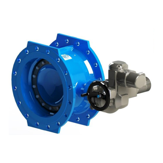
Jelajahi secara online atau unduh pdf Panduan Pengoperasian untuk Unit Kontrol Jafar 4493. Jafar 4493 14 halaman. Double eccentric flanged butterfly valve

6. OPERATION
The valve shall be operated in accordance with all relevant requirements for stop valves.
To ensure full operational efficiency, carry out a technical inspection and maintenance at least once a year as
follows:
•
Operate the valve from the fully open position to the fully closed position, or vice versa.
•
If the valve operation is difficult, i.e. the valve reaches the maximum driving torque before either of its
limit positions, repeat the full operation three times (by opening and closing the valve repeatedly).
•
Check the tightness of all connections and seals with the valve closed.
If all the actions above have been completed with a good result, visually inspect the corrosion protection. If the
paint coat is damaged, rebuild it with the paint kits available from JAFAR.
Exceeding the operating limits of the valve may result in damage that will not covered by the warranty or the
statutory warranty granted by the manufacturer. When controlling butterfly valves 4493 fitted with a JFR part-turn
gearboxes, the torque limits given in Table 5 below must be strictly adhered to:
DN
200
M
[Nm]
46
maks
Number of turns
10
Table 5. Maximum torque on the gearbox shaft and the total number of rotations to the open-close position.
Replacing the seal in the flap.
In order to replace the sealing ring of the flap, it is recommended to remove the butterfly valve from the pipeline,
while observing the relevant health and safety regulations.
Before replacing the seal (4), the product must be fully closed. This will make it easier to dismantle the
compression ring (5).
7
3
OPERATING MANUAL
250
300
350
400
46
109
175
175
10
9
10
10
07-2022
500
600
700
800
197
134
123
123
14
55
93
93
6
In the first stage, the transmission
control element (wheel or drive)
must be removed to
accidental
5
changing the butterfly valve
position to horizontal. Then place
the butterfly valve body (2) on a
4
solid surface, e.g. a pallet (1) as
presented in the drawing (with the
compression
2
upwards). The next step is to clean
the seat of the welded body, the
1
flap (3), the compression ring
from any dirt and contaminants.
Remove the retaining screws (7),
then
alternately
retaining screws with the spring
washers (6) from the flap (3).
900
1000
1200
151
151
153
117
117
218
avoid
damage
when
ring
facing
remove
the
13/14
