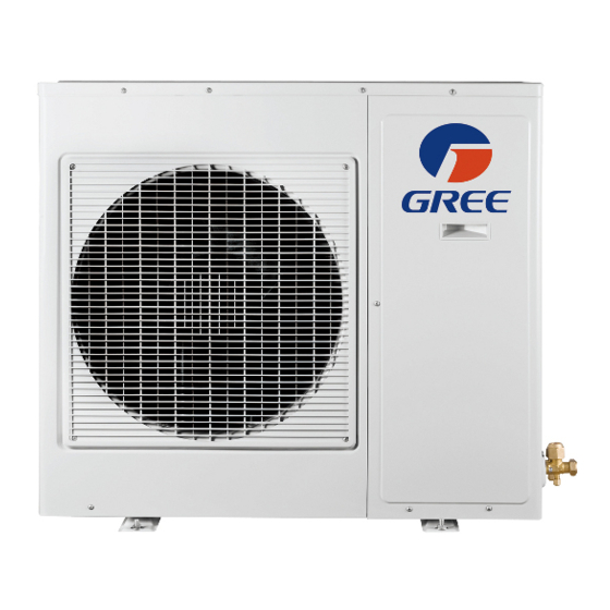
Gree GWHD(24)ND3CO Panduan Instalasi - Halaman 3
Jelajahi secara online atau unduh pdf Panduan Instalasi untuk Pompa Panas Gree GWHD(24)ND3CO. Gree GWHD(24)ND3CO 16 halaman. Multi
ductless inverter
Juga untuk Gree GWHD(24)ND3CO: Panduan Pemilik (11 halaman)

- 1. Heat Pump
- 2. Installation Manual
- 3. Table of Contents
- 4. Safety Precautions
- 5. System Requirements
- 6. Suggested Tools
- 7. Site Instructions
- 8. Dimensions
- 9. Indoor Unit
- 10. Outdoor Unit
- 11. Refrigerant Piping
- 12. Refrigerant Piping
- 13. Power and Wiring
- 14. Vacuum Testing
- 15. Start-Up
- 16. Troubleshooting
SAFETY PRECAUTIONS
C UTION
• The unit should be installed and serviced only by trained, qualified installers and service
mechanics. Untrained personnel can perform basic maintenance functions such as
cleaning coils.All other operations should be performed by trained service personnel.
• Owner should be cautioned that children should not play with the appliance.
W RNING
ELECTRICAL SHOCK HAZARD
Failure to follow this warning could result in personal injury or death.
• Before installing, servicing or modifying the system, the main electrical disconnect switch
must be in the OFF position.There may be more than one disconnect switch. Lock out
and tag all switches with a warning label.
General Safety Precautions
• A dedicated power supply circuit should be used in accordance with local electrical
safety regulations and National Electrical Codes (NEC).
• Ensure that the entire system is reliably grounded.
• Use proper size circuit breaker to protect equipment against short circuit and
overload conditions.
• The system must be positioned at least 5 feet from combustive surfaces.
• Observe all local codes and regulations.
INSTALLATION SITE INSTRUCTIONS
Proper installation site is vital for correct and reliable operation of the system.
Avoid the following installation locations:
• Strong heat sources, vapors, flammable gas or volatile liquids.
• High-frequency electro-magnetic waves, generated by radio equipment, welders
or medical equipment.
SYSTEM REQUIREMENTS
Piping Requirements
OUTDOOR UNITS in (mm)
Unit Size (BtuH)
18,000
24,000
30,000
36,000
42,000
INDOOR UNITS in (mm)
Unit Size (BtuH)
9,000
12,000
18,000
REFRIGERANT PIPE LENGTHS
Unit Size
Min Pipe
(BtuH)
Length ft(m)
18,000
10 (3)
24,000
10 (3)
30,000
10 (3)
36,000
10 (3)
42,000
10 (3)
REFRIGERANT CHARGE
Unit Size
Refrigerant
(BtuH)
18,000
24,000
30,000
36,000
42,000
*Precharge amount for up to 25-ft of refrigerant pipe.
ELECTRICAL REQUIREMENTS
Unit Size
Voltage
(BtuH)
18,000
208/230v - 1ph 60hz
24,000
208/230v - 1ph 60hz
30,000
208/230v - 1ph 60hz
36,000
208/230v - 1ph 60hz
42,000
208/230v - 1ph 60hz
**Main power wire from electrical panel to outdoor unit.
Notes:
1) System must be on a single dedicated circuit.
2) Main power is supplied to the outdoor unit.
3) Use table above to size over current protection.
4) Follow all local building codes and NEC (National Electrical Code) regulations.
Interconnecting Cable: Recommended cable - 14/4 AWG stranded bare copper conductors THHN 600V unshielded wire
Note: Use shield cable if installation is in close proximity of RF and EMI transmitting devices.
3
Condensate Drain Size: 5/8-in OD 7/16-in ID
Note: Insulate condensate drain hose to prevent sweating and possible water damage.
Liquid Line in (mm)
Port 1
1/4 (6)
Port 2
1/4 (6)
Port 1
1/4 (6)
Port 2
1/4 (6)
Port 3
1/4 (6)
Port 1
1/4 (6)
Port 2
1/4 (6)
Port 3
1/4 (6)
Port 4
1/4 (6)
Port 1
1/4 (6)
Port 2
1/4 (6)
Port 3
1/4 (6)
Port 4
3/8 (9.5)
Port 1
1/4 (6)
Port 2
1/4 (6)
Port 3
1/4 (6)
Port 4
1/4 (6)
Port 5
3/8 (9.5)
Liquid Line in (mm)
Suction/Gas Line in (mm)
1/4 (6)
1/4 (6)
1/4 (6)
Max Total Pipe
Max Equivalent
Max Elev btwn
Length ft(m)
Pipe Length ft(m)
IND Units ft
66 (20)
33 (10)
16
230 (70)
66 (20)
33
230 (70)
66 (20)
33
230 (70)
82 (25)
50
262 (80)
82 (25)
50
Factory System
Type
Charge oz (kg)*
R410A
48 (1.4)
R410A
78 (2.2)
R410A
78 (2.2)
R410A
102 (2.9)
R410A
169 (4.8)
Min Circuit
Max Overcurrent
Amps (MCA)
Protection (MOP)
13
20
20
30
26
45
28
45
29
50
Suction/Gas Line in (mm)
3/8 (9.5)
3/8 (9.5)
3/8 (9.5)
3/8 (9.5)
3/8 (9.5)
3/8 (9.5)
3/8 (9.5)
3/8 (9.5)
3/8 (9.5)
3/8 (9.5)
3/8 (9.5)
1/2 (12)
5/8 (16)
3/8 (9.5)
3/8 (9.5)
1/2 (12)
1/2 (12)
5/8 (16)
3/8 (9.5)
3/8 (9.5)
1/2 (12)
Max Elev btwn
IND & OTD Units ft(m)
33 (10)
66 (20)
66 (20)
82 (25)
82 (25)
Additional
Charge oz/ft (g/m)
0.2 (20)
0.2 (20)
0.2 (20)
0.2 (22)
0.2 (22)
Main Power
Wire Size (AWG)**
12
10
8
8
6
4
