AIRFIX 5014429200052 Petunjuk Manual - Halaman 5
Jelajahi secara online atau unduh pdf Petunjuk Manual untuk Mesin AIRFIX 5014429200052. AIRFIX 5014429200052 16 halaman. Jet engine

Assembly sequence 52
Assembly sequence 53
Assembly sequence 54
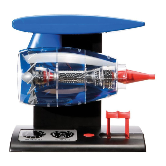
jet engine
Assemble the 1st stage compressor
blades, numbers 1 and 2, the cone,
spacer and spindle washer onto the
spindle as indicated.
Please make sure that you
assemble the correct size blades
(SHORT).
Assemble the smaller 2nd stage
compressor blades with the spacer
and coned blade to the rear, as
indicated, onto the spindle.
Assemble the 1st stage turbine
blade with coned end facing forward
and fit the mating turbine blade No.
1, with collar, also facing forward.
Assemble the larger 2nd stage
turbine blades. The coned end of
the first turbine blade faces forward
and the mating turbine blades,
numbers 1, 2, and 3 are fitted with
their collars also facing forward.
Please make sure that you
assemble the correct size blades
(LONG).
With the turbine blades in position
fit the end cap with collar facing
forward into the recess of the rear
mating turbine blade.
24
Position the lever arms, voltage
regulator and circuit board into the
base unit
Push the lever slides onto the lever
arms
Overview of the electric cable connections
between the base unit and base cover after
assembly
Connect the RED wire from the voltage
regulator (speed control) to battery terminal
"B" with the nut and screw provided.
Connect the BLACK wire from the starter
switch to the BLACK wire from the voltage
regulator (speed control) by twisting together
and covering with sleeve as shown in
sequence 10.
Connect the red wire from the starter switch
to battery terminal "C" with the nut and screw
provided.
(Nut and screws connections are to be used on wires
with ring terminals.)
See assembly sequences 10 to 18 for the correct
method of connecting the electric cables
Assembly sequence 7
Assembly sequence 8
Assembly sequence 9
BLACK
A
RED
BLACK
RED
RED
C
B
9
