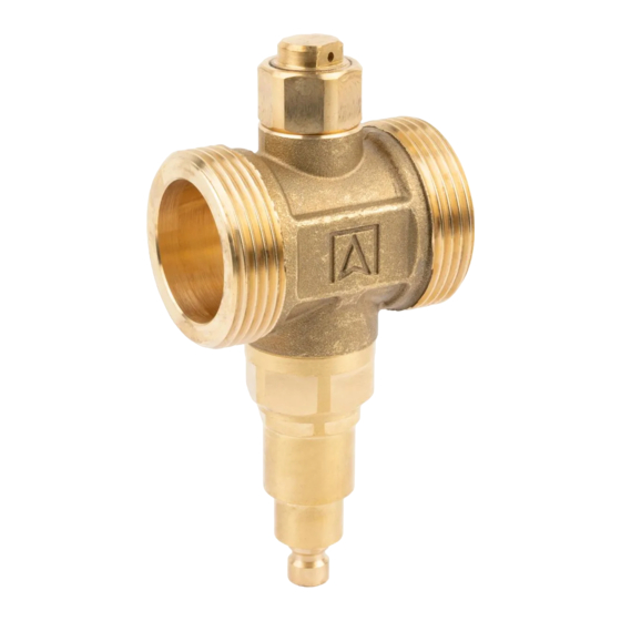
AFRISO 17 100 00 Buku Petunjuk - Halaman 2
Jelajahi secara online atau unduh pdf Buku Petunjuk untuk Unit Kontrol AFRISO 17 100 00. AFRISO 17 100 00 2 halaman. Anti-freeze valve aav

MONTAGE
The AAV anti-freeze valve should be installed on the return and supply pipelines in a vertical position,
in the coldest part of the system (between the building wall and the outdoor unit of the heat pump).
For proper operation, the valve should not be thermally insulated and located near heat sources that
could negatively affect to its operation. In addition, the valves should not be mounted one above the
other. Between the valves should be min. 10 cm of horizontal clearance. The flowing medium from the
upper valve, which will hit the valve located below may freeze and block the draining of the medium
properly through the lower valve. Do not mount the valve directly on the ground. Keep a min. 20 cm cle-
arance, so that the created ice does not block the drainage of water from the valve
should be shielded from the direct influence of atmospheric conditions, which can lead to its incorrect
operation.
Fig. 4 MINIMAL DISTANCE BETWEEN THE BOTTOM OF THE VALVE AND THE GROUND
Created ice
Between the valve and the external unit of the heat pump, must not be any siphoned pipeline sections,
which can cause a disturbance in the outflow of the medium from the system. In this case, the pipes may
not be fully drained and the protection against freezing will not be ensured
with a constant slope toward the valve
(Figure
on the proper operation of valves in the system, it is recommended to install a magnetic dirt separator
(Art.-No 77 180 00) and application of a corrosion inhibitor (Art.-No 90 700 00) in the installation.
Fig. 5 UNACCEPTABLE PIPE ROUTING DUE TO SIPHONED SECTIONS
Fig. 6 ACCEPTABLE INSTALLATION POSITION AND PIPE ROUTING IN THE SYSTEM
(Figure
4). The valve
min. 20 cm
(Figure
5). Lead the pipes
6). In order to minimize the impact of any impurities
APPROVALS AND CERTIFICATES
Anti-freeze valves AAV complies with the Pressure Directive PED 2014/68/EU and according to article 4.3
(sound engineering practice) must not wear the CE mark
TECHNICAL DATA
Parameter
Opening temperature
Closing temperature
Accuracy
Operating temperature range
Ambient temperature range
Operating pressure
Kvs (depending on the version)
Connections (depending on the version)
Body material
Spring material
Sealing material
MAINTENANCE
Warning! Maintenance operations should be done only after the installation will completely
cooled down.
The AAV valve is a completely maintenance-free. In case of water leaks through the vacuum breaker,
it is possible to replace it with a new one (Art.-Nr. 17 000 03). If the thermostatic cartridge malfunctions,
replace the cartridge together with the thermostatic element (for AAV 100 valve Art.-No. 17 000 01, for
AAV 300 valve (Art.-No 17 000 02). In order to replace the cartridge with the thermostatic element and/
or the vacuum breaker, first disconnect the AAV valve from the rest of the system by closing the flow
on the nearest shut-off valves. Then unscrew the defective element from the valve and screw in a new
one.After the replacement is completed, open the shut-off valves and check the pressure in the system.
If necessery fill the instalation with medium.
DECOMMISSIONING, DISPOSAL
1.
Dismount the product
2.
To protect the environment, this product must not be disposed of together with normal household
waste. Dispose of the product in accordance with the local directives and guidelines.
Anti-feeze valves AAV consist of materials that can be recycled
WARRANTY
Product warranty in accordance with the general conditions of sale and delivery
CUSTOMER SATISFACTION
Customer satisfaction is our prime objective. Please contact us if you have any questions or problems
concerning our product: [email protected], phone: 32 330 33 55.
3
4
Value / material
3°C
4°C
±1°C
0÷70°C
-30÷60°C
max 10 bar
AAV 100 - 55 m
/h
3
AAV 300 - 70 m
3
/h
AAV 100 - G1"
AAV 300 - G1¼"
brass CW617N
stainless steel
EPDM
