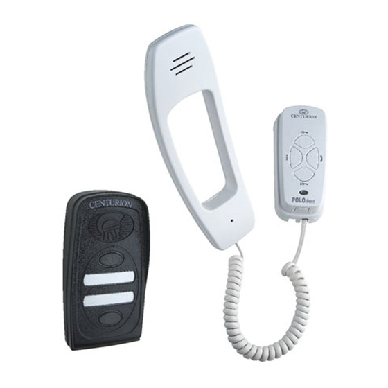
Centurion POLOphone Panduan Instalasi - Halaman 6
Jelajahi secara online atau unduh pdf Panduan Instalasi untuk Sistem interkom Centurion POLOphone. Centurion POLOphone 17 halaman. Entry panel
Juga untuk Centurion POLOphone: Panduan Instalasi (16 halaman), Panduan Instalasi (17 halaman), Prosedur Komisioning (4 halaman)

Power supply & wiring
Power Supply
The POLOphone system operates off a 14V DC supply. The system is designed so that power can be
connected to any one of the components in the system.
If the system is being installed with a gate operator that can provide at least a 12V DC 150mA supply,
the entry panel can be connected directly to this unit.
If the 12V DC gate motor supply dips when the motor starts up and the intercom is being used at
the same time, the speech quality might be affected.
Alternatively if battery power is not available at the entry panel, CENTURION offers a 14V DC supply
(mains adapter), (order ref: POLOP000V1) that plugs into a universal two pin 220 to 240V AC mains
supply socket.
A DC jack is provided on the output of the adapter that plugs conveniently into the cradle of any one of
the handsets in the system.
Terminals are provided on the cradle electronic module to terminate a 14V DC supply should the
supply being used not have a jack compatible with the socket on the cradle.
If the bus voltage (between terminals "1" and "2") is lower than 8V DC, power needs to be applied at
another unit in the system.
Wiring
Wiring
The two wire bus of the POLOphone system is polarised. If incorrectly connected the unit will not
operate, but it will not be damaged.
The length of the bus is limited to a maximum of 150m.
It might be necessary to double up on the thickness of the two wire bus depending on the distance
between the entry panel and handsets in the system, and to which component the power supply is
connected (handset or entry panel). Refer to page 7 for the cable thickness schedule.
Two Wire Bus
Fig 2 Wiring Requirements
Page 6 - POLOphone Intercom
Additional wiring required for Auxiliary and Status LED
TRG
