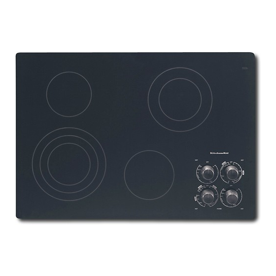
KitchenAid KECC051HWH04 Panduan Petunjuk Instalasi - Halaman 4
Jelajahi secara online atau unduh pdf Panduan Petunjuk Instalasi untuk Kompor KitchenAid KECC051HWH04. KitchenAid KECC051HWH04 16 halaman.

Before You Make the Electrical Connection:
To properly install your cooktop, you must determine the type of
electrical connection you will be using and follow the instructions
provided for it here.
A 4-wire or 3-wire, single phase, 240-volt, 60-Hz., AC-only
electrical supply is required on a separate, 40-amp circuit,
fused on both sides of the line.
NOTE: The KECC051 model series requires a 20-amp circuit.
The cooktop should be connected directly to the junction box
through flexible, armored or nonmetallic sheathed, copper
cable. The flexible, armored cable extending from the fuse box
or circuit breaker box should be connected directly to the
junction box.
Locate the junction box to allow as much slack as possible
between the junction box and the cooktop so that the cooktop
can be moved if servicing becomes necessary in the future.
Do not cut the conduit. Use the length of conduit provided.
A UL listed or CSA approved conduit connector must be
provided at each end of the power supply cable (at the
cooktop and at the junction box). A listed conduit connector is
already provided at the cooktop.
If the house has aluminum wiring, connect the aluminum
wiring to the copper wire by using special connectors
designed and UL listed for joining copper to aluminum. Follow
the electrical connector manufacturer's recommended
procedure. Aluminum/copper connection must conform with
local codes and industry accepted wiring practices.
Prepare Cooktop for Installation
WARNING
Excessive Weight Hazard
Use two or more people to move and install cooktop.
Failure to do so can result in back or other injury.
1. Decide on the final location for the cooktop. Locate existing
wiring to prevent drilling into or severing wiring during
installation.
2. Using two or more people, place the cooktop upside down on
a protective surface.
3. Remove foam strip from literature packing. Remove backing
from foam strip. Apply foam strip adhesive-side down around
bottom of cooktop, flush with edge.
NOTE: The foam strip protects the underside of the cooktop
glass from debris and helps the cooktop sit flat on uneven
counters.
A. Burner box
B. Foam strip
4
Style 1: Cooktop over undercounter built-in oven
IMPORTANT: Clamp brackets should not be used.
1. Turn cooktop right side up.
2. Place cooktop in cutout.
NOTE: Make sure that the front edge of the cooktop is parallel
to the front edge of the countertop. If repositioning is needed,
lift entire cooktop up from cutout to prevent scratching the
countertop.
Style 2: Cooktop over cabinets
1. Determine whether your cabinet construction provides
clearance for installing clamp brackets at burner box ends.
This is the recommended location. Clamp brackets can be
installed on the front and back of burner box bottom, if
necessary.
A
B
2. The clamp brackets can be installed before or after the
cooktop is placed into the cutout. Complete the following
steps for the option you choose.
Installing Brackets Before Placing Cooktop in Cutout
1. Remove the attachment screws for the selected bracket
locations from the bottom of the burner box.
2. Select bracket mounting holes that will allow the bracket to
extend far enough out from the cooktop for the installation of
2½" (6.4 cm) clamping screws. See "Attach Cooktop to
Countertop" for illustration of clamping screw installation.
A
B
3. Attach brackets to burner box bottom with bracket
attachment screws using the bracket mounting holes selected
in Step 2.
4. Rotate brackets so they do not extend beyond edge of burner
box.
Install Cooktop
A. Attachment screw holes for optional front and back
location.
B. Clamp bracket (end locations recommended)
C. Burner box bottom
D. Attachment screw
E. Attachment screw location (recommended)
A. Edge of burner box bottom
B. Clamp bracket
C
D
E
A
B
