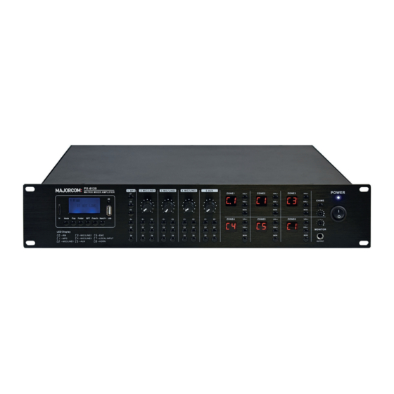
Majorcom: PX-6120 Panduan Pengguna - Halaman 4
Jelajahi secara online atau unduh pdf Panduan Pengguna untuk Penguat Majorcom: PX-6120. Majorcom: PX-6120 8 halaman. 6*6 zones matrix amplifier with mp3/fm/bluetooth player

6
PX-6120
6*6 ZONES MATRIX AMPLIFIER WITH MP3/FM/BT PLAYER
2.3 BACK PANEL
24
21
22
23
(21)
AC power outlet
(22)
Zone Output-100V & 8Ω
(23)
Booster output of the 6 zones
(24)
Release monitoring in CAR
(25)
EMC Entry (Priority Entry Type ARM-911A)
(26)
Entrance AUX
(27)
Mic 1/Line 1 input
3. USER GUIDE
3.1 CONNECTION AND CONFIGURATION
With the P X-6120 powered off (20), connect the rear IEC jack (21) to the MAINS using the supplied AC
cable (or equivalent approved type). Verify that the voltage is correct and that the speaker connection is
correct, then turn on the device.
The P x-6120 has 5 input channels and a built-in multi-source audio player.
Mic inputs 1, 2 and 3 are designed to receive microphones or line-level sources (such as a CD/mp3 player
or the output of a mixer) via combo connectors on the back panel, they are switchable by DIP switch.
They can accept XLR or 6.35mm jack plugs for balanced or unbalanced signals.
User manual
5 6 , c h e m i n d e l a F l a m b è r e • 3 1 3 0 0 To u l o u s e • F R A N C E • T é l . 3 3 ( 0 ) 5 6 1 3 1 8 6 8 7
F a x 3 3 ( 0 ) 5 6 1 3 1 8 7 7 3 • c o m m e r c i a l @ m a j o r c o m . f r • w w w . m a j o r c o m . f r
29
32
25
26
27
28
30
31
(28)
Mic 2/Line 2 input
(29)
Bass and treble control
(30)
Mic 3/Line 3 input.
(31)
RJ45 interface for microphone panel and vo-
lume deck.
(32)
FM antenna
(33)
24VDC input to trigger the reading of a
message or sound cut
6*6 ZONES MATRIX AMPLIFIER WITH MP3/FM/BT PLAYER
3.2 DIP SWITCHES
Mic/line inputs 1, 2 and 3 each have 2 DIP switches on the back panel to adjust the input level and/or en-
able the +20V phantom power supply for the use of condenser microphones.
Set the level correctly for the type of input source connected (microphone or line).
If the connected source is a condenser microphone that requires phantom power, make sure phantom is
enabled for that channel.
Be sure to make these DIP switch settings when the amplifier is turned off.
3.3 ACTIVATION OF PRIORITIES AND EMERGENCIES
33
1.
MESSAGE (HORN) - trigger on 24VDC, the message is activated (or sound cut)
2.
EMC input - emergency priority audio input
3.
RM-6000 Microphone Panel
4.
Other local entry
3.4 SIGNAL INPUTS AND OUTPUTS
Connect microphones or line signals to Mic/Line 1, 2 and 3 inputs (27, 28, 30) using good quality audio
cables. A stereo or mono line level source can be connected to the input of auxiliary channel 4 on 2 RCA
connectors (26).
To check the output of any area, an assignable Monitor output can be connected to headphones from the
6.35mm jack on the front panel (15).
(15) or as a line output (e.g. to active speakers) from the RCA connectors on the back (24).
Each zone output has a dedicated RCA signal output on the back panel (23), which can be connected to
the line inputs of active speakers or booster amplifiers. These outputs are in addition to the speaker out-
puts detailed below.
An antenna input (32) is provided on the back panel for connection to an external antenna for FM tuning
There are bass and treble controls on the back panel to adjust the sound of the MIC and Line input signal.
5 6 , c h e m i n d e l a F l a m b è r e • 3 1 3 0 0 To u l o u s e • F R A N C E • T é l . 3 3 ( 0 ) 5 6 1 3 1 8 6 8 7
F a x 3 3 ( 0 ) 5 6 1 3 1 8 7 7 3 • c o m m e r c i a l @ m a j o r c o m . f r • w w w . m a j o r c o m . f r
PX-6120
7
Manuel d'utilisation
