bern NFPA-13R Instruksi Instalasi dan Pengoperasian - Halaman 3
Jelajahi secara online atau unduh pdf Instruksi Instalasi dan Pengoperasian untuk Beralih bern NFPA-13R. bern NFPA-13R 4 halaman. Waterflow alarm switch
b) Grinding
Deburrs to make the hole edge smooth.
Clean the pipe after grinding, no other material inside or outside of the pipe
c) Field Installation
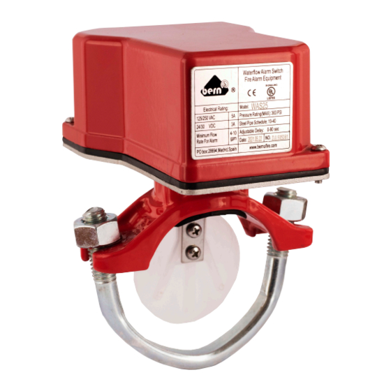
Select the correct Waterflow alarm switch corresponding to the pipe diameter.
Check the direction of the water flow, make sure the arrow direction on the saddle same as the Waterflow alarm switch direction.
The arrow direction must be same as the water flow direction, otherwise, the water flow indicator cannot start and function properly.
Roll the vane, insert the vane into the hole, press the locating slot into the hole, make sure the rubber gasket must be in the locating slot
when installed horizontally, the water flow indicator should be at the top of the pipe or side of the pipe, not at the bottom of the pipe.
d) Fasten the Bolts
Mount the U-bolts, fasten the nuts alternately, keep the sealing surface between saddle and pipe evenly. Switch the rod to verify if
the vane can be active or not. If the vane acts slowly, perform above steps again.
Rod
Do not exert force to the signal part when fastening, otherwise, the signal part will be damaged.
e) Electrical Wiring
The Waterflow alarm switch (WAS) has two switches, one can be used to operate a central control station, proprietary or remote
signaling unit, while the other contact is used to operate a local audible or visual annunciator.
Field Wiring Diagram
Cut off the power source when wiring, an uninsulated section of a single conductor should not be looped around the terminal
and serve as two separate connections. The wire must be severed, not exposed outside.
3
Waterflow Alarm Switch
Installation and Operation Instruction
CAUTION
CAUTION
www.bernofire.com
.
WARNING
WARNING
supply@bernofire.com