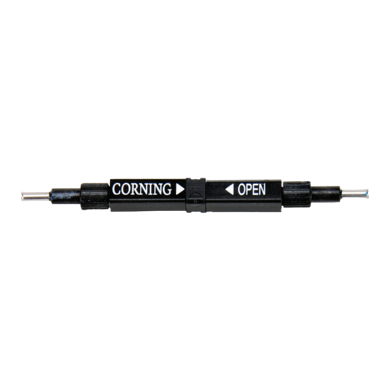
CORNING CamSplice FBC-017 Perakitan - Halaman 8
Jelajahi secara online atau unduh pdf Perakitan untuk Peralatan Laboratorium CORNING CamSplice FBC-017. CORNING CamSplice FBC-017 10 halaman. Splicer

c) Pull back on the right fiber and then
remate it against the left fiber. Once inward
pressure is felt, rotate the right lever to 45
degrees (Figure 14) and recheck the loss.
d) Steps a - c can be performed up to 2 times
to optimize the splice. If after 2 attempts,
the loss is still unacceptable, remove the
fibers and re-prepare the fibers as per
Section 4, Preparing Cable and Fiber.
e) If the loss is acceptable, rotate both cams
to 90 degrees as shown in Figure 12 and
continue with the procedure to finish the
installation.
7.
Completing CamSplice Assembly
7.1
Crimp Lead-in Tube
Step 1:
If direct terminating on 250 micron
fiber: Slide furcation tubing into the
lead-in tube on each side of the splice
until the tubing stops.
Step 2:
Capture lead-in tube inside the
notched area of the crimp tool. Crimp
lead-in tube on each side of the splice
with the tool.
7.2
Remove Completed CamSplice from Tool
Step 1:
Gently release the fibers from both
clamps.
Step 2:
Working from the right side of the
assembly tool, carefully lift the
CamSplice out of the tool (Figure 16).
Step 3:
If using boots, slide both boots up until
they reach the cam of the CamSplice.
Step 4:
Secure the CamSplice in its splice tray
or hardware.
Step 5:
Follow the instructions provided with
the splice tray or hardware to ensure
that the splice and its fibers are
properly strain-relieved.
STANDARD RECOMMENDED PROCEDURE 006-383 | ISSUE 1 | AUGUST 2008 | PAGE 8 OF 10
45°
KPA-2103
Figure 14 — Rotate Right Lever
Direct Termination -
250 micron
Applications
Only
Slide
Furcation
Tube
KPA-2096
Figure 15 — Crimp Lead-in Tube
KPA-2093
Figure 16 — Lift CamSplice out of Tool
