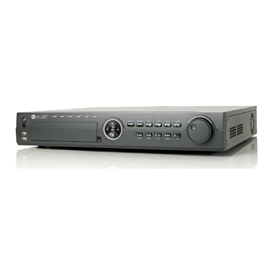
ALIBI ALI-HVR5016H Panduan Pengaturan Cepat - Halaman 4
Jelajahi secara online atau unduh pdf Panduan Pengaturan Cepat untuk DVR ALIBI ALI-HVR5016H. ALIBI ALI-HVR5016H 9 halaman. 16-channel hd-tvi digital video recorder

Wiring alarm outputs to the DVR
The DVR provides 4 alarm output terminations. These terminations for each output are on the ALARM OUT connector block on the back of the
DVR , and are labeled 1 - G, 2 - G, 3 - G, 4 - G (G = ground termination).
There are 4 jumpers (JP1, JP2, JP3, and JP4) inside the chassis on the alarm termination PC board, associated with ALARM OUT pins 1, 2, 3
and 4 respectively. Initially, these jumpers are in place. If connecting an alarm output to a DC loaded alarm out circuit, the jumper must be in
place. If connecting the alarm output to an AC loaded alarm, the corresponding jumper must be removed. Example: If you connect an AC load
to the alarm output 3 of the DVR, then you must remove the JP 3.
To remove a jumper for AC load alarm circuits:
1.
Disconnect all cabling from the DVR.
2.
Remove the DVR top cover. For more information, refer to the ALI-HVR5016H 16-Channel HD-TVI Digital Video Recorder User
Manual provided electronically with your systems.
3.
Locate the jumper associated with the alarm output you are using for an AC load alarm, then remove it. Save the jumper for use later,
if needed.
4.
Reinstall the DVR top cover.
DC load alarm output circuits
DC loads must operate within the limitation of 12V/1A. To connect to a DC alarm output, use the following diagram:
DVR
AC load alarm output circuits
To connect an AC load to an alarm output, a jumper, associated with the output on the alarm termination PC board, (within the chassis), must
be removed. These jumpers shunt pin pairs J1, J2, J3, and J4 for alarm outputs 1, 2, 3, 4 respectively. Use an external relay for safety.
DVR
4
www.Observint.com
DC Load
Step 2. Install a monitor, mouse, power
For the following steps, refer to the back panel photo above for the location of connectors.
1.
Install and setup your monitor in accordance with the instructions provided with the monitor. Do not power it on at this time.
2.
Cable the HDMI or VGA connector to your monitor's VGA or HDMI input. The HDMI interface provides the best performance.
3.
Plug the mouse into the USB connector on the front or back of the DVR.
4.
If you plan to access your DVR remotely, or configure your DVR to transmit alerts, email, etc. to external servers, plug a drop cable from
your local area network (LAN) into the RJ45 LAN connector on the back of the DVR.
5.
Connect the power cord to the power connector on the back panel of the DVR, and then into a UPS (preferred) or surge protector.
NOTE
Do not power on the DVR at this time.
Step 3. Connecting it together – initial system setup
1.
Plug the coaxial cables from the cameras into the BNC camera input connectors on the back of the DVR.
2.
Power on the DVR using the power on / off (I / O) switch on the back panel.
3.
Power on the monitor.
Some monitors have multiple inputs such including VGA ,HDMI, BNC, etc. If you are using this kind of monitor, configure your monitor to
NOTE
display the input connected to your DVR (HDMI or VGA).
4.
Power on your cameras.
Step 4. Using the Wizard for basic configuration setup
1.
Power on the DVR. Normally, an Alibi logo splash screen appears within 2 minutes. A secondary flash screen will appear showing the
status of the HDDs installed in the DVR.
© 2014 Observint Technologies. All rights reserved.
