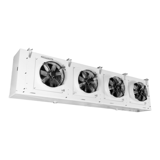
FRIMETAL FRM Buku Petunjuk - Halaman 8
Jelajahi secara online atau unduh pdf Buku Petunjuk untuk Pendingin Udara FRIMETAL FRM. FRIMETAL FRM 20 halaman. Industrial evaporators

¡PRECAUCION!
Durante las operaciones de conexión de los ventiladores ase-
gurarse de que la corriente de alimentación eléctrica esté
desconectada mediante un interruptor de seguridad que no
se pueda volver a conectar accidentalmente.
1-CAJA DE CONEXION DEL VENTILADOR
Cada ventilador lleva una caja de conexiones situada en el
centro de la rejilla y accesible desde el exterior quitando los
tornillos de la tapa. Con el fin de facilitarle al instalador la
conexión, los ventiladores van cableados de fábrica a una
caja de plástico IP-55 situada en un extremo del aparato
donde quedan todas las conexiones centralizadas.
Se adjuntan los dibujos con las conexiones en las cajas de
los ventiladores con los siguientes elementos:
1 Regleta de conexiones de 9 terminales
2 Manguera con los cables que salen del motor
3 Manguera con 6 cables que sale hacia la caja de conexio-
nes exterior. Estos cables corresponden a las tres fases de
la línea L1, L2 y L3, los dos cables del termocontacto TK y
el cable de conexión a tierra PE.
4 Puentes que se pueden cambiar para tener conexión
(alta velocidad estándar de fábrica) ó
Este esquema de conexiones viene también en una pegatina
colocada en el interior de la tapa de la caja de conexiones de
cada ventilador.
8
During the fan motor connecting operation make sure that the
electric current is disconnected by means of a security switch
so as to prevent an accidental start.
1-JUNCTION BOX ON THE FAN MOTOR
Each fan motor has an individual junction box situated in the
centre of the grille and accessible from the outside by simply
removing the screws of the lid. In order to facilitate the con-
nection to the installer, the fan motors are wired from factory
to a plastic junction box IP-55 placed on one end of the unit
where all the electric connections are centralized.
Below there is a drawing of a fan motor showing the plastic
junction box in the middle with the following elements:
1 Terminal strip with 9 connections
2 Cable with the wires coming from the motor
3 Cable with 6 wires coming out to the external junction box.
4 Removable bridge-wires to change from connection
(baja velocidad).
The fan motor connection drawing is also displayed in a label
stuck on the inner side of each junction box lid.
WARNING!
These wires correspond to the three-phase line L1,L2 and
L3, the two thermocontact TK wires and the ground con-
nection PE wire.
(high-speed factory standard) to
(low speed).
