Jandy Jandy Pro Series Manual - Halaman 6

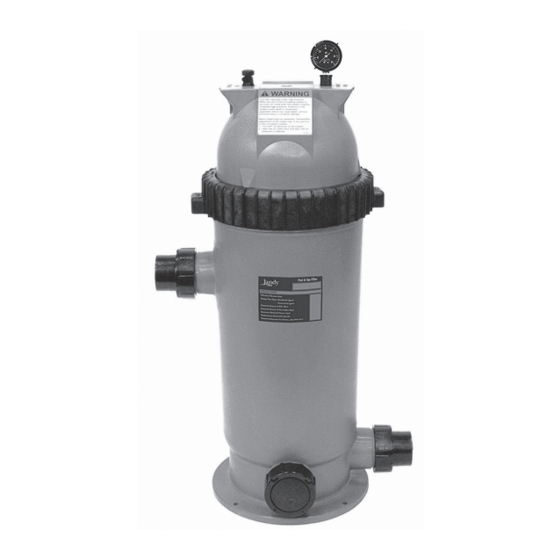
Jelajahi secara online atau unduh pdf Manual untuk Filter Kolam Renang Jandy Jandy Pro Series. Jandy Jandy Pro Series 8 halaman. Single element cartridge pool & spa cs filters
Juga untuk Jandy Jandy Pro Series: Panduan Pemilik (12 halaman), Panduan Instalasi (16 halaman), Panduan Instalasi dan Pengoperasian (20 halaman), Panduan Pemilik (20 halaman), Panduan Memulai Cepat (2 halaman), Panduan Instalasi dan Pengoperasian (20 halaman), Petunjuk Instalasi (2 halaman), Panduan Instalasi dan Pengoperasian (16 halaman), Panduan Instalasi dan Pengoperasian (16 halaman), Panduan Instalasi dan Pengoperasian (16 halaman)

Jandy Jandy Pro Series Manual
Page 6
Comm Hole
Figure 9.
Accessing and Wiring to the Power PCB
7. In the AquaLink RS or PDA power center, wire the
power pack directly to the LOAD SIDE of the filter
pump relay (see Figure 10 and 12).
8. The AquaLink RS or PDA and power pack use a
four (4) wire connection to communicate and can be
wired up to 500 feet apart. Any outdoor rated four
conductor cable, minimum 22 AWG, can be used.
Locate the appropriate screw terminals on the circuit
board and wire the power pack to the AquaLink RS
or PDA red 4-pin terminal bar
(see Figure 11).
NOTE The screw terminals on the AquaLink RS or
PDA are removable to aid in installation.
Jandy
Pro Series AquaPure
Ei™ Series
®
®
AquaLink RS or PDA Power Center
To Filter Pump
(240 VAC)
Cable Tie
To Filter Pump
(120 VAC)
Figure 10.
Red, 4-Pin
Terminal Bar
Figure 11.
|
Replacement Kit Instructions
240 VAC
Filter Pump Relay
Aux. 3 Relay
To Breaker
Panel
120 VAC
Filter Pump Relay
Aux. 3 Relay
To Breaker
Panel
Wiring Power Pack to an AquaLink RS
or PDA Power Center (240 VAC and 120
VAC)
4 3 2 1
OPTIONAL
Jandy
Power Center
Communication Wiring between Power
Pack and AquaLink
®
or PDA Network
To Power Pack
(240 VAC)
To Power Pack
(120 VAC)
Power Pack
GRN
YEL
BLK
RED
RS Control System