Jandy Jandy Pro Series Panduan Instalasi dan Pengoperasian - Halaman 9

Jelajahi secara online atau unduh pdf Panduan Instalasi dan Pengoperasian untuk Filter Kolam Renang Jandy Jandy Pro Series. Jandy Jandy Pro Series 20 halaman. Single element cartridge pool & spa cs filters
Juga untuk Jandy Jandy Pro Series: Panduan Pemilik (12 halaman), Panduan Instalasi (16 halaman), Panduan Instalasi dan Pengoperasian (20 halaman), Panduan Pemilik (20 halaman), Manual (8 halaman), Panduan Memulai Cepat (2 halaman), Petunjuk Instalasi (2 halaman), Panduan Instalasi dan Pengoperasian (16 halaman), Panduan Instalasi dan Pengoperasian (16 halaman), Panduan Instalasi dan Pengoperasian (16 halaman)
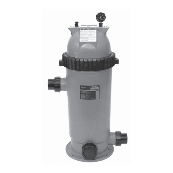
Jandy Jandy Pro Series Panduan Instalasi dan Pengoperasian
Jandy Pro Series Levolor
II Electronic Water Leveler
®
Models K-2100
3.5

Installing the Valve and Relay

NOTE Install the valve with the directional water flow
arrow pointing in the appropriate direction. The
directional water flow arrow is located on the
inlet side of the valve.
A 24VAC solenoid valve will provide water from a
supply line to the fountain (or other environment:
cooling tower, pond, reservoir, storage tank, etc.).
You can install the supply line either before or after the
filter at the equipment pad or on a dedicated line back to
the fountain.
Zodiac recommends a minimum 1" valve and an anti-
siphon valve, which provides inexpensive insurance
against accidental draining of the fountain (or other
environment).
Always use an in-line strainer, which can be purchased
from Zodiac.
1.
Connect the 24VAC water solenoid valve to the
18-gauge solid-core burial cable using grease-
filled wire nuts.
2.
Connect the wires from the Fill Valve to the blue
wires in the control box using wire nuts. See
Figure 7, page 10.
3.
Connect the wires from the Low Water Cutoff
AC Relay Coil to the red wires in the control box
using wire nuts. See Figure 7, page 10.
4.
Turn the flow control knob (+) on the top of the
valve (See Figure 5) to set the flow rate to your
specifications. (The rate can be set up to 30 GPM.)
5.
Put the manual ON/OFF lever, located just below
the solenoid, in the OFF position, so it can only be
opened by the electronic water Levolor.
See Figure 6.
|
Installation and Operation Manual
Figure 5. Valve Flow Controller
ON
Manual
On/Off Lever
Manual Filling
Figure 6. Manual Valve Lever
Page 9
ENGLISH
Flow Control
OFF
Manual
On/Off Lever
Controlled Filling