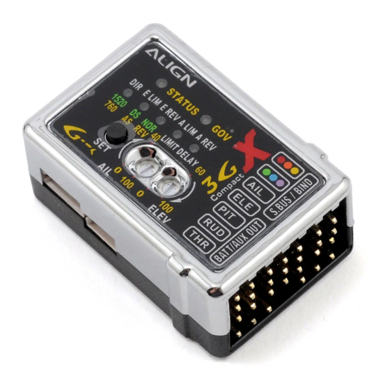
Align 3GX V2.1 Pengaturan - Halaman 4
Jelajahi secara online atau unduh pdf Pengaturan untuk Unit Kontrol Align 3GX V2.1. Align 3GX V2.1 4 halaman. Easy setup table

Swashplate Settings
Setting 6
LED
Setting
Setup Method
Transmitter
Setting
Setup Method
Warnings
After completing setting of 8 degrees SWASH, do
not make further adjustments. If adjustment to
helicopter's roll rate is needed, the adjustment
must be made in the roll rate under flight mode's
cyclic pitch section.
3GX V2.1 Easy Setup Table (English).xlsx
Align 3GX V2.1 ‐ Setup Summary
Speed Governor Settings
D du Rand ‐ July 2012
Rudder Settings
LED 1~5 all lit up
Gyro install reverse setting
1. To achieve consistent gyro gain on left and right, 3GX has
built in anti‐torque compensation function. User need to
confirm if 3GX is mounted right side up or upside down.
2. Right side up: Installed with 3GX label facing up, anti‐torque
compensation set to positive (green STATUS LED). Upside
down: Installed with 3GX label facing down, anti‐torque
compensation set to negative(red STATUS LED).
4. Setup method: Press and hold the SET button for 2 seconds
to enter setup mode, select until anti‐torque compensation
section, as indicated by lighting of all 5 setup mode LEDs. Using
the rudder stick to select either positive anti‐torque
compensation (green STATUS LED) for right side up mounting,
or negative anti‐torque compensation (red STATUS LED)for
upside down installation.
In addition to transmitter, the anti‐torque compensation
feature can also be set through 3GX interface's rudder
parameter.
Rudder Gain Adjustment on Transmitter
1. For radio with built in gyro gain settings, gain can be adjusted
directly. For example, 50%‐100% setting on the radio
translates to 0% ‐ 100% gain in the heading lock mode; 50%‐0%
setting on the radio translates to 0%‐100% gain in the normal
(non‐heading) lock mode.
2. Actual gain value differs amongst servos and helicopters.
The goal is to find the maximum gain without tail hunting. This
can only be done through actual flight tests.
3.The recommended starting point for transmitter's gyro gain
setting should be 70~80% for hovering, 60~70% for idle‐up.
Value should be tuned under actual flight conditions by
increasing to the maximum gain without tail hunting.
Flight Mode Setting
1. Flashing LED indicates 10%; fully lit LED indicates 20%. For
example, LED1 and LED2 are fully lit, while LED3 is flashing, this is
translated to 2*20+10=50%.
2. Move the stick to display the stick function's setting value. For
example, moving aileron stick will result in LED1~LED5 displaying
aileron's setting value.
Deon du Rand ‐ 2012‐7‐04
4 of 4
