Alinx ALTER AC4075 Panduan Pengguna - Halaman 14
Jelajahi secara online atau unduh pdf Panduan Pengguna untuk Perangkat Keras Komputer Alinx ALTER AC4075. Alinx ALTER AC4075 19 halaman. Core board
ALINX ALTERA Core Board AC4075 User Manual
Figure 5-3: Expansion Ports P1&P2 on the Core Board
Part 6: Power interface on Core Board
In order to make the core board work normally, the FPGA expansion board
needs to provide a +5V power supply to the core board through the expansion
ports. The power supply voltage of the core board ranges from 4.5V to 5.5V,
and the current is about 1A. In order to ensure a certain margin, the FPGA
carrier board It is best to provide 5V 2A current. The FPGA carrier board
provide the 5V power input to the core board through pin 1 to 4 of the
expansion port P1, P2.
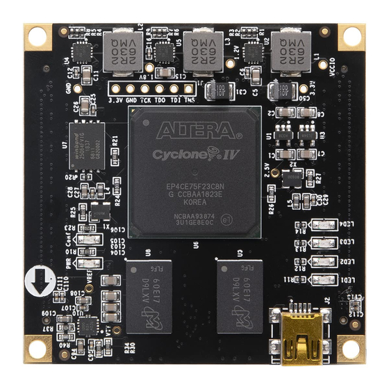
Figure 6-1: Power input pin
Amazon Store: https://www.amazon.com/alinx
14 / 19