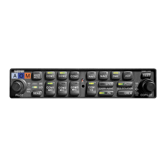
Garmin GMA 340 Panduan Instalasi - Halaman 15
Jelajahi secara online atau unduh pdf Panduan Instalasi untuk Tampilan Avionik Garmin GMA 340. Garmin GMA 340 43 halaman. Audio panel
Juga untuk Garmin GMA 340: Panduan Pilot (12 halaman), Panduan Pengoperasian Tambahan (10 halaman), Panduan Pilot (4 halaman), Panduan Pilot (8 halaman), Panduan Pilot (8 halaman), Panduan Pilot (12 halaman)

2.5
REAR CONNECTIONS
2.5.1
Location
The GMA 340 has two 44 pin connectors located at the rear of the unit, designated J1 and J2. J1 and J2 pin
assignments are given in table 2-1. When viewed from the back of the rack, J1 and J2 look like the following:
These notes apply to the following table:
* Denotes Active Low. (Ground to activate).
GMA 340
** The GMA 340 provides inputs for an unswitched aircraft radio (TEL
RINGER) and an un-muted, unswitched aircraft radio (ALT WRN).
GMA 340 Installation Manual
190-00149-01
J2
Figure 2-1. Rear Connectors
interconnect wiring diagrams.
NOTES
Refer to Figures B4 through B7 for
J1
Page 2-3
Rev. L
