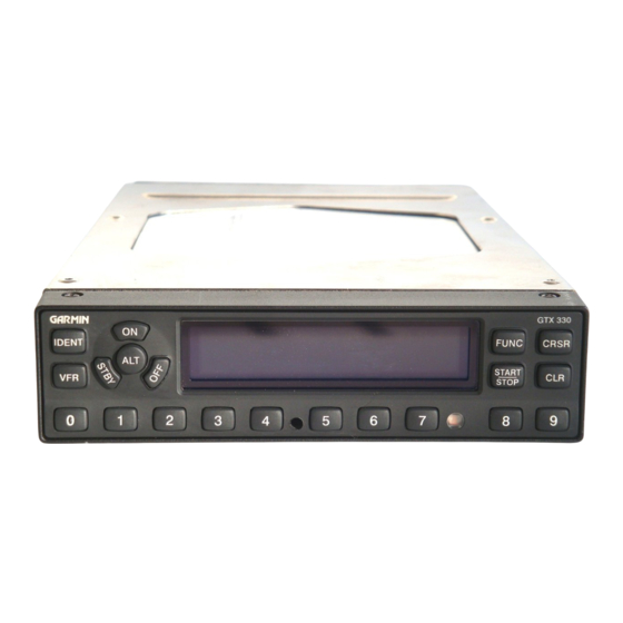
Garmin 010-00230-00 Panduan Instalasi - Halaman 34
Jelajahi secara online atau unduh pdf Panduan Instalasi untuk Radio Kelautan Garmin 010-00230-00. Garmin 010-00230-00 49 halaman.

BKLT SRCE (Backlight Source)
Selection
PHOTO (Photocell)
14V
28V
5V
If a lighting bus (any selection other than PHOTO) is selected, and the lighting bus control is
turned to its minimum (daytime) setting, the display brightness will track the GTX 330 photocell.
SLOPE
Sets the sensitivity of the display brightness to changes in the input level. The higher the number, the brighter the
display will be for a given increase in the input level. This field has a range of 0 (zero) to 99, and is set to 50 at the
factory.
OFFSET
Adjusts the lighting level up or down for any given input level. This field has a range of 0 (zero) to 99, and is set to
50 at the factory. This may also be used to match lighting curves with other equipment in the panel.
5.2.6 KEY LIGHTING Page
The key lighting mode is always the same as the display backlight mode,
so the mode must be changed on the Display Backlight configuration
page. If the lighting mode is AUTO, then the key lighting parameters
can be edited on this page.
KEY (Key Lighting)
Selection
MAN (Manual)
AUTO (Automatic)
LVL (Level)
Shows the current level of key lighting, based on the lighting input source (lighting bus voltage, or the ambient light
if the source is PHOTO) and the settings on this configuration page. This field has a range of 0 (zero) to 999, but is
not a user-entered field (display only).
GTX 330 Installation Manual
190-00207-02
Description
DEFAULT. Backlight level is determined by the ambient light level
as measured by the photocell on the GTX 330.
Backlight level tracks a 14 volt DC aircraft lighting bus.
Backlight level tracks a 28 volt DC aircraft lighting bus.
Backlight level tracks a 5 volt DC aircraft lighting bus.
Description
Key lighting is controlled manually by the pilot on the GTX 330
DISPLAY page.
Key lighting is automatically controlled based on the parameters
entered on this configuration page.
NOTE
KEY LIGHTING Page
Page 5-7
Rev. 1
