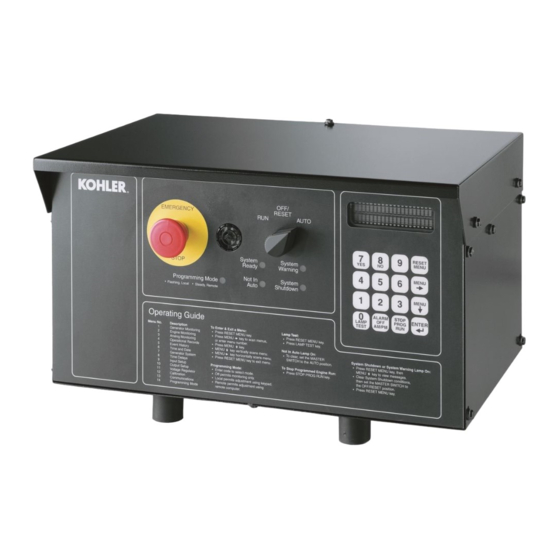
Kohler 20-3250 kW Operasi - Halaman 17
Jelajahi secara online atau unduh pdf Operasi untuk Generator Portabel Kohler 20-3250 kW. Kohler 20-3250 kW 20 halaman. Industrial generator sets

System Warning. Yellow lamp identifies an existing
fault condition that does not shut down the generator set.
A continuing system warning fault condition may cause
a system shutdown. Correct all system warnings as
soon as practical.
See Section 2.3.5, System Warning Lamp, for
definitions of the items listed.
The following conditions cause a system warning:
D
Engine functions:
d
ECM yellow alarm
(DDC/MTU engine with MDEC/ADEC)
d
High battery voltage
d
High coolant temperature
d
Low battery voltage
d
Low coolant temperature
d
Low fuel (level or pressure)*
d
Low oil pressure
d
Speed sensor fault
d
Starting aid (system status)
d
Weak battery
D
General functions:
d
Auxiliary—Analog up to 7 user-selectable inputs
each with a high and low programmable warning
level
d
Auxiliary—Digital up to 21 user-selectable
warnings
d
Battery charger fault*
d
Emergency power system (EPS) supplying load
d
Engine cooldown delay
d
Engine start delay
d
Load shed kW overload
d
Load shed underfrequency
d
Master switch not in AUTO (automatic start)
position
d
NFPA 110 fault (National Fire Protection
Association)
d
System ready (system status)
D
Alternator functions:
d
AC sensing loss
d
Ground fault*
d
Overcurrent
* Requires optional input sensors.
Note: See Figure 2-8 in User Inputs for factory-
reserved analog and digital inputs that are not
user-selectable.
TP-6200 10/12
System Shutdown.
generator set has shut down because of a fault
condition. The unit will not start without resetting the
controller,
see
Section
Procedure.
See Section 2.3.6, System Shutdown Lamp, for
definitions of the items listed.
The following conditions cause a system shutdown:
D
Engine functions:
d
Air damper closed (status), if equipped
d
Coolant temperature signal loss
d
ECM red alarm
(DDC/MTU engine with MDEC/ADEC)
d
Engine stalled (ECM only)
d
High coolant temperature
d
High oil temperature
d
Low coolant level
d
Low oil pressure
d
Oil pressure signal loss
d
Overcrank
d
Overspeed
D
General functions:
d
Auxiliary—Analog up to 7 user-selectable inputs
each with a high and low programmable
shutdown level
d
Auxiliary—Digital up to 21 user-selectable
shutdowns
d
ECM communications loss (ECM models only)
d
Emergency stop
d
Internal fault
d
Master switch in OFF/RESET position
d
Master switch error
d
Master switch open
d
NFPA 110 fault
D
Alternator functions:
d
AC output overvoltage
d
AC output undervoltage
d
Alternator protection against overload and short
circuits
d
Field overvoltage
(M4, M5, M7, or M10 alternator only)
d
Locked rotor (failed to crank)
d
Overfrequency
d
Underfrequency
Note: See Figure 2-8 in User Inputs for factory-
reserved analog and digital inputs which are
not user-selectable.
Section 1 Specifications and Features
Red lamp indicates that the
2.3.7,
Controller
Reset
17
