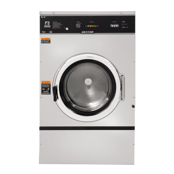
Dexter Laundry WCVD Series Pemecahan Masalah dan Kode Kesalahan - Halaman 7
Jelajahi secara online atau unduh pdf Pemecahan Masalah dan Kode Kesalahan untuk Mesin cuci Dexter Laundry WCVD Series. Dexter Laundry WCVD Series 18 halaman.

Fault# Description
F13
The variable frequency
drive (VFD) and the
washer computer are not
communicating.
F14
Over-current on the drive or
motor.
F15
The variable frequency
drive (VFD) senses that
the internal voltage is too
high. The source of the
problem can originate from
two different areas. Area
1: The input voltage can be
too high, or there may be a
high level of electrical noise.
Area 2: The motor can be
generating a voltage that is
acting like an input to the
VFD output motor terminals.
Customer Action
Check the data communication cable between the
washer computer and the variable frequency drive
(VFD).
Step 1: Make sure the cable did not become
unplugged during operation.
Step 2: Make sure that the cable is not being pulled
sideways at either the washer controller, or the VFD,
plug end. If both ends of the communications cable are
plugged in the washer computer and VFD and there is
no tension on the communications cable pulling it from
side to side, then replace the cable.\
Step 3: Inspect both female connection points at PCB
controller and at VFD. These may need replacement if
they cannot be reset.
Step 1: Check to make sure the washer cylinder turns
freely by hand. If it turns freely, continue to step 2. If
it does not, remove the belt and see if the motor turns
freely by hand. If the motor turns freely, then check for
obstructions in the cylinder or check the bearings. If
the motor does not turn freely, replace the motor.
Step 2: Check the motor wires for a short circuit
between leads. If there are motor leads that have
conductors touching, separate them and insulate them.
If the wires are broken, splice them together or replace
the motor.
Step 3: Check braking resistors to see if they measure
the correct resistance. If a resistor does not measure
the proper value, replace it.
Step 1: Measure the supply voltage to the VFD on
the L1, L2 (or N), and L3 (if connected to three phrase
power). the supply voltage should be from 187 to
264 VAC or 108 to 132 VAC for a 120 VAC VFD. Also
make sure the supply wires on L1, L2 (or N) and
L3 (if connected to three phase power are securely
connected.
Step 2: Ch eck the braking resistor connections at the
VFD. The terminal screws should be tight. Once of the
braking resistor wires should be connected to terminal
B2.
Step 3: Measure each braking resistor separately to
make sure they are the correct resistance. (200 for 1
and 2 Hp VFD and 160 for 3 Hp VFD).
Step 4: If you have a 240 VAC, high leg voltage
supply, try disconnecting the high leg. If this cures
the problem, either leave the high leg disconnected,
connect a transient voltage surge suppressor (with
some form of fi ltering) at the voltage supply panel,
connect a line choke on the high leg or install a VFD
fi lter.
7
Part # 8533-074-001 09/13
