DeZurik APCO SRG-6500 Buku Petunjuk - Halaman 4
Jelajahi secara online atau unduh pdf Buku Petunjuk untuk Unit Kontrol DeZurik APCO SRG-6500. DeZurik APCO SRG-6500 11 halaman. Surge relief globe valves

DeZURIK
APCO SRG-6500 Surge Relief Globe Valves
Description
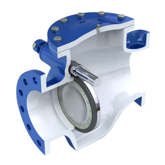
The Surge Relief Globe valve consists of a Body, Disc, Seat, Counterweights and a Cushion Cylinder.
Surge pressure above that for which the valve was set, will open the disc, causing the counterweight
arm and cylinder piston to rise to the up position. As the piston rises in the cushion cylinder, oil is drawn
into the cushion chamber from the oil reservoir through the flow control valve. The amount that disc will
open depends on the surge pressure and velocity of the media flowing through the valve.
Handling and Storage
Lifting the valve improperly may damage it. Do not fasten lifting devices to the cylinder or through the
seat opening in the body. Lift the valve with slings, chains or cables fastened around the valve body, or
fastened to bolts or rods through bolt holes in the flanges.
If installation will be delayed, place valve indoors in secure, weather tight storage. If temporary outside
storage is unavoidable, make sure a vermin proof rain cover (water shedding tarp, etc.) is secured
around/over the valve to keep off rain and mud. Skid and set the assembly on a flat, solid, and well
drained surface for protection from ground moisture, runoff and pooled rain water.
Installation
•
All Surge Relief valves are delivered to the jobsite, factory adjusted and ready for installation. It
should always be installed with the replaceable resilient seat of the disc facing the system
pressure. The valve outlet must be piped to discharge into the wet well or into a spillway.
•
Valve may be installed in a horizontal or vertical position with the flow upward. In either case,
counterweight arm (44) should always be in the horizontal position and the oil reservoir (58), in
the vertical position. The counterweight (29) is set at the factory for the relief pressure setting
specified by the customer.
•
Adjustments within the design range of the valve can be made in the field by moving the
counterweights along the counterweight arms. Moving the counterweights away from the pivot
shaft will increase relief pressure setting and vice versa.
•
Before installation, remove foreign material such as weld spatter, oil, grease, and dirt from the
pipeline.
Prepare pipe ends and install valves in accordance with the pipe manufacture's instructions for
•
the joint used.
Do not deflect the pipe-valve joint. Minimize bending stresses in the valve end
connection with pipe loading.
If excessive seat leakage occurs during start-up, recheck the installation and
eliminate any distortion to the valve body.
•
Ensure the valve and pipeline flanges are concentric to ensure proper flange sealing and seat
leakage control.
•
Tighten the flange bolts or studs in a crisscross pattern and minimum of four stages.
D12020
Page 4
December 2012
