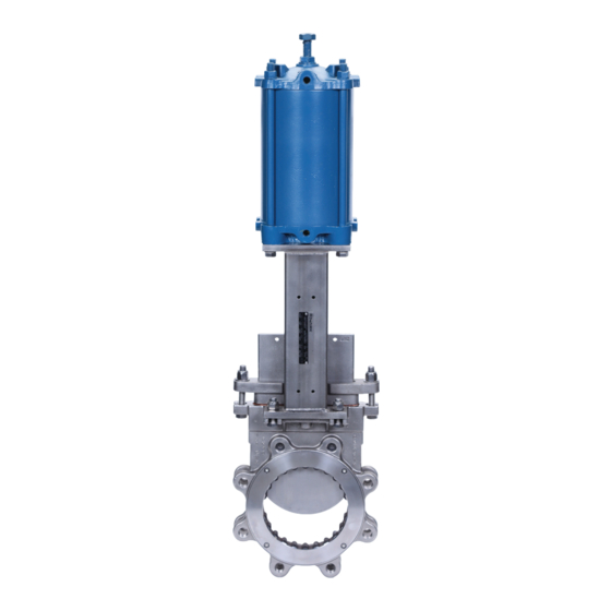
DeZurik KGC-MC Petunjuk Manual - Halaman 13
Jelajahi secara online atau unduh pdf Petunjuk Manual untuk Unit Kontrol DeZurik KGC-MC. DeZurik KGC-MC 17 halaman. Metal cutting knife gate valves

DeZURIK
KGC-MC METAL CUTTING KNIFE GATE VALVES
Replacing the Gate
6. Remove and inspect the seat components.
7. Replace or reinstall the seat components as described in the "Seat Replacement" section.
8. Place the new gate (A3) in the body, in the fully closed position.
9. Replace or reinstall the scraper rings (A2) and packing (A8) as described in "Installing New
Packing".
10. Replace the yoke and actuator on the valve.
11. Adjust the actuator, yoke, and packing gland so that the valve actuates smoothly full stroke in
both directions, and so that there is no evidence of binding or scratching on the gate when the
gate is visible in the fully open position.
12. Reinstall the valve in the pipeline as described in the "Installation" section.
13. Reconnect power to the actuator.
14. Pressurize the pipeline and inspect the valve for leaks.
15. If the packing leaks, tighten the adjustment nuts (A7) on top of the packing gland. Tighten the nuts
evenly and slowly, just enough to stop the leakage. Over tightening will cause excessive operating
forces, and will decrease the life of the packing.
Replacing the Clip
For KGC-MC metal cutting valves with a pneumatic cylinder actuator, the clip and gate are match
drilled to handle high frequency cycling. If the clip needs to be replaced, the following steps would be
necessary to achieve a proper fit between the clip, gate and shoulder bolts:
1. Prior to disassembly of the previously utilized clip from the gate and pneumatic actuator, measure
the gap between the jam nut and the clip as shown in Figure 7. This distance will be utilized when
reassembling the jam nut onto the new clip.
2. For valve sizes 3" through 8", drill the clip holes to .500" [12.7mm]; for valve sizes 10" through 24",
drill the clips holes to .625" [15.88mm] and confirm the fit of the two shoulder bolts through the clip.
3. Place the clip on to the gate and roughly align the clip holes with the gate holes.
4. Insert a shoulder bolt all the way through the clip and gate. At this time, do not tighten the nut onto
the shoulder bolt.
5. Try to insert the second shoulder bolt all the way through the clip
and gate. It is common that due to the match drilling of the
previous clip to the gate, the second shoulder bolt may not fit
through the gate. In this case, with the first shoulder bolt still
inserted and using the clip's second hole as a guide, drill through
the clip and gate. The hole sizes in the gate are .500" [12.7mm]
for valve sizes 3" through 8"; and .625" [15.88mm] for valve sizes
10" through 24".
6. Insert the second shoulder bolt all the way through the clip and
gate.
7. Remove the shoulder bolts from the clip and thread the jam nut
onto the clip to the distance measured previously.
November 2020
continued
Page 13
Figure 7
D11060
