DeZURIK
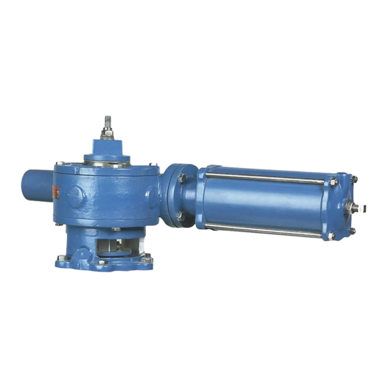
Cylinder Operated G-Series Actuator
Reassembling Actuator
19. Replace the extension cap.
20. Check the stop settings and readjust if necessary. The correct adjustment procedure is
described in the STOP ADJUSTMENT Section of this instruction.
21. Pipeline flow may now be restored.
Changing Mounting Positions
The actuator can be mounted in 30° increments around the valve shaft. 30° position changes require
changing the timing between the gear sector and the rack; 60° position changes do not require
changing the timing.
When tapered plug valves are mounted in a vertical pipeline, or mounted in a horizontal pipeline with
the plug stem horizontal, gravity can cause the plug to swing to a lower position in the valve body when
the actuator is removed. To avoid this problem, place the plug in the lowest position before removing
the actuator.
Mounting Actuator in 60° Increments
1. Remove the actuator from the valve. See "Removing Actuator" section.
Accidental operation of power actuator can cause personal injury or equipment damage.
Disconnect and lock out power to actuator before servicing.
2. Disconnect and lock out the pneumatic power to prevent accidental operation of the actuator.
3. Rotate the actuator into position.
4. Install the actuator on the valve. See "Installing Actuator".
Mounting Actuator in 30° Increments
1.
Discontinue flow and relieve pipeline pressure.
Accidental operation of power actuator can cause personal injury or equipment damage.
Disconnect and lock out power to actuator before servicing.
2. Disconnect and lock out the pneumatic power to prevent accidental operation of the actuator.
3. Remove the lock nut from the top of the wrenching square.
4. Remove the four socket head screws and wrenching square.
5. Note the position of the pointer, then remove the two socket head screws and slide the pointer
off the actuator.
6. Remove the plug adjusting nut from the stud and slide the bearing washer off the stud.
7. Note the stampings on the top of the valve plug stem. These stampings correspond with the
plug face as shown in Figure 3. It is important that the plug position be noted to ensure it is in
the correct position during actuator installation.
D10191
(Continued)
Page 12
July 2016

