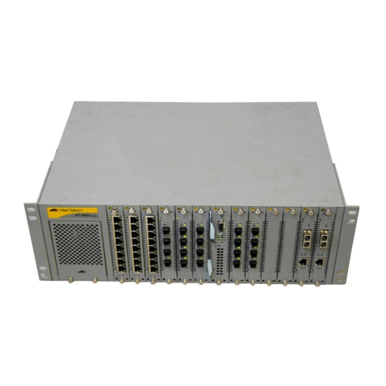
Allied Telesis AT-8400 Series Panduan Instalasi
Jelajahi secara online atau unduh pdf Panduan Instalasi untuk Beralih Allied Telesis AT-8400 Series. Allied Telesis AT-8400 Series 2 halaman. Line card and power supply
blank faceplate
Juga untuk Allied Telesis AT-8400 Series: Panduan Instalasi (2 halaman)

AT-8400 Line Card and Power Supply
Blank Faceplate
Installation Guide
For use with the AT-8400 Chassis
Allied Telesyn, Inc.
Visit our web site at: www.alliedtelesyn.com
Overview
AT-8400 blank faceplates are designed to maintain optimal, trouble-free
environmental conditions for the AT-8400 chassis. This installation guide
provides instructions for installing both the line card blank faceplate and
the power supply blank faceplate.
The AT-8400 chassis requires a blank faceplate installed in every chassis slot
that is not occupied by an Ethernet line card. The blank faceplate (see
Figure 1) keeps dust from getting into the switch and maintains proper
airflow throughout the chassis.
Figure 1. Line Card Blank Faceplate
PN 613-50540-00 Rev A
1
The AT-8400 chassis also requires a blank faceplate installed in any power
supply slot not occupied by a power supply. The power supply blank
faceplate (see Figure 2) ensures proper cooling and ventilation of the
AT-8400 chassis.
Figure 2. Power Supply Blank Faceplate
Related Documents
For complete details regarding the features, functions, and installation
instructions for the AT-8400 Chassis, refer to the AT-8400 Series Switch
Reference Guide (part number 613-50399-00) which is available from the
Allied Telesyn web site at www.alliedtelesyn.com.
Package Contents
Make sure the following items are included in your shipping package. If any
item is missing or damaged, contact your Allied Telesyn sales repre-
sentative.
❑
Three AT-8400 line card blank faceplates
❑
One AT-8400 power supply blank faceplate
❑
Installation Guide
Installing the AT-8400 Line Card Blank Faceplate
You can install an AT-8400 line card blank faceplate whether the chassis is
powered on or powered off.
Caution
Before installing an AT-8400 blank faceplate, refer to the AT-8400
Series Switch Reference Guide for electrical safety information.
To install an AT-8400 line card blank faceplate, perform the following
procedure:
1. Select the slot in the AT-8400 chassis where you need to install a blank
faceplate. You can install the faceplate in any slot marked 1 through 12.
2
Caution
Do not install a blank faceplate in Slot M. Slot M is reserved for the
AT-8401 Management Fabric Card.
2. Unpack a blank faceplate from the shipping package, and store any
unused blank faceplates in a safe location.
Caution
Observe all standard electrostatic discharge (ESD) precautions, such
as wearing an antistatic wrist strap, to avoid damaging the chassis
device. Line cards can be damaged by static electricity.
3. Verify that the blank faceplate package includes all the items previously
listed in "Package Contents" on page 2. If any item is missing or
damaged, contact your Allied Telesyn sales representative for
assistance.
4. Align the edge of the blank faceplate with the top and bottom guide
rails before carefully sliding the faceplate into the slot, as shown in
Figure 3. Slide the faceplate forward into the slot until the faceplate is
flush with the front of the chassis.
AT -8
40 0
Mo dul
ar Sw
itch Sys
tem
1
2
AT -84
3
11
PWR
AT -84
4
11
PWR
AT -84
11
PWR
PWR
LNK
10
ACT
EJEC
100
T
LNK
ACT
10
EJEC
T
100
LNK
ACT
EJEC
10
T
100
EJEC
Figure 3. Insertion of Line Card Blank Faceplate
5. Secure the blank faceplate to the chassis by using a Phillips screwdriver
to tighten the two installation screws on the faceplate.
Note
Always tighten the installation screws to secure the blank faceplate to
the switch chassis. Leaving a faceplate partially seated can still allow
dust to enter the chassis and disrupt the normal air flow.
You have completed the line card blank faceplate installation procedure.
3
5
AT -84
11
LNK
10
ACT
100
T
