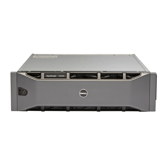
Dell EqualLogic PS5000 Pemeliharaan Perangkat Keras - Halaman 30
Jelajahi secara online atau unduh pdf Pemeliharaan Perangkat Keras untuk Server Dell EqualLogic PS5000. Dell EqualLogic PS5000 46 halaman. Storage arrays
Juga untuk Dell EqualLogic PS5000: Manual Perangkat Keras (50 halaman)

PS5000 Hardware Maintenance
Once you remove a control module, place it on a surface that is protected from
electrostatic charge.
If the array will permanently operate with only one control module, you must
install a blank control module in the empty slot. You can order a blank from your
array support provider. For proper cooling, do not leave a control module slot
empty.
Installing a Control Module
You may need to install a control module as part of an upgrade from a single
control module array to a dual control module array or for control module
maintenance, such as replacing a failed control module.
Notes: You can upgrade to a dual control module array without shutting down the
array.
Only install control modules of the same type in a PS5000 array, either
Type 4 or Type 5. Do not mix control module types in an array.
Make sure the control module type is compatible with the disk type.
Type 4 control modules are used only with SAS disks (black disk release
button).Type 5 control modules are used only with SATA disks (gray disk
release button).
Control modules are installed vertically in a PS5000 array, with the latch
mechanism facing the adjacent power supply and cooling module
Before removing a control module:
•
Make sure the firmware on the control module's compact flash card matches
the firmware running on the already-installed control module. See
Maintaining Control Module Firmware on page 3-4.
•
If you are replacing a failed control module, be sure to remove the compact
flash card from the failed control module and install it in the replacement
control module. This will ensure that the new control module is running the
correct firmware.
•
If you are upgrading to a dual control module array, remove the blank control
module from the slot. See the instructions in Figure 3-5 for opening the latch.
•
Attach an electrostatic wrist strap (see Using an Electrostatic Wrist Strap on
page 1-4).
To install a control module, refer to the instructions in Figure 3-6.
3–10
Maintaining Control Modules
