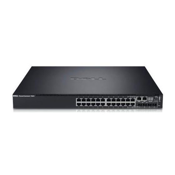
Dell PowerConnect PC7024P Petunjuk Penumpukan - Halaman 26
Jelajahi secara online atau unduh pdf Petunjuk Penumpukan untuk Beralih Dell PowerConnect PC7024P. Dell PowerConnect PC7024P 37 halaman. Stacking gigabit ethernet switches
Juga untuk Dell PowerConnect PC7024P: Buku Putih Teknis (34 halaman)

Stacking Dell PowerConnect 7000 Series Switches
To take full advantage of nonstop forwarding, layer 2 connections to neighbors should be via port
channels that span two or more stack units, and layer 3 routes should be ECMP routes with next hops
via physical ports on two or more units. The hardware can quickly move traffic flows from port channel
members or ECMP paths on a failed unit to a surviving unit.
Initiating a Warm Failover of the Manager Unit
You can use the initiate failover command to initiate a "warm" restart. This command reloads
the management unit, triggering the standby unit to take over. As the standby management unit takes
over, the system continues to forward end-user traffic. The end-user data streams switched over the
failing switch may lose a few packets during the failure, but they do not lose their IP sessions, such as
VoIP calls.
If no standby unit is available when the initiate failover command is issued, the command fails
with an error message stating that no standby unit exists. If the standby unit is not ready for a warm
restart, the command fails with a similar error message.
Administrators should be aware that use of the movemanagement command is not recommended in
operational networks as network traffic interferes with stack convergence. The movemanagement
command performs a full synchronization and then triggers a cold restart, even if the target unit is the
backup unit, and is therefore less preferred than the initiate failover command.
Nonstop Forwarding Scenario
Figure 5 depicts the following network setup:
Host 1 is a video stream server. Hosts 2 and 3 are video stream receivers.
The stack has OSPF and PIM-SM adjacencies with Router 1 over a LAG with member
ports in unit 1 and unit 2.
Spanning tree runs on the links in the L2 network connecting the stack, Switch 1, and
Switch 2.
The stack runs IGMP on the links toward Host 2 and Host 3.
VLAN 20 is a routing VLAN with IP address 192.168.20.2 on the stack.
The network is configured to select Switch 2 as the root bridge. The stack selects its
direct link to Switch 2 as its root port. The stack puts its link to Switch 1 in the
Discarding state.
Router 1 is a Cisco router that serves as a static rendezvous point (RP) in the PIM-SM
network.
The CLI for configuring this scenario follows the illustration, along with a description of how the stack
responds during a failover with NSF enabled and disabled.
Page 24
