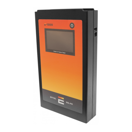
Entec Solar E-1000 Panduan Memulai Cepat - Halaman 11
Jelajahi secara online atau unduh pdf Panduan Memulai Cepat untuk Alat Ukur Entec Solar E-1000. Entec Solar E-1000 17 halaman.

Module or generator
The user must disconnect the test circuit from any other element that it may be
connected. Not doing this may cause serious damage to the device or the test circuit.
Use the cables provided with the device to connect it to the test circuit. It is made out
of two red wires and two black wires that dame a 4-point connection.
First connect the four banana plugs (two red and two black) to the device. The red
color is the positive pole of the test circuit and the black color is the negative pole.
The provided wires have an MC4 ending to direct connect to solar photovoltaic
modules.
The cables provided with the device have been manufactured with the proper mate-
rial to allow to connect them directly. As a result, the positive pole (red wire) has a
female MC4 terminal, and the negative pole (black wire) has a male MC4 terminal.
There is also a special adapter with crocodile endings to connect to other elements,
like for example a bus-bar from a combiner box, if it may be necessary.
IMPORTANT: A wrong connection of the positive or negative pole of the test
circuit with the device may cause permanent damage to the device. The red
color means the positive pole of the test circuit and the black color means
the negative pole of the test circuit.
ATTENTION: During these maneuvers there is risk of electrical shock. It is
mandatory to use the personal protection elements to reduce this risk to the
minimum and properly perform the established sequence to disconnect the test
circuit from the rest of the elements.
Figure 4. Connection of E-1000 to the test circuit.
11
"Innovative technological developments for the solar photovoltaic industry"
Figure 5. Proper connection to E-1000.
www.entecsolar.es
