360 Vision Vision i Dome Panduan Instalasi & Konfigurasi - Halaman 8
Jelajahi secara online atau unduh pdf Panduan Instalasi & Konfigurasi untuk Kamera Keamanan 360 Vision Vision i Dome. 360 Vision Vision i Dome 20 halaman.
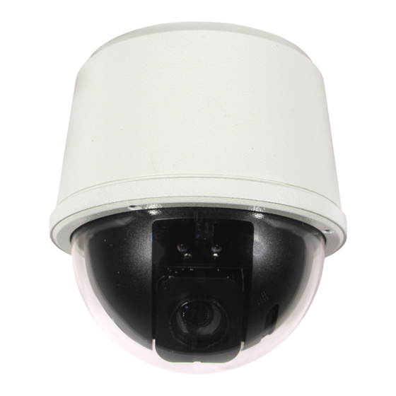
Vision i Dome_VisionDome VR Installation Manual Ver 3.1
The VRVD-XALARM-PSU has eight normally open/normally closed (Dilswitch S1, switch 8 on) alarm inputs
on connector CON1 on the alarm PCB. When using normally closed contacts, all un-used alarm inputs must
be connected to alarm in common CON1. Connect switches or volts free relay outputs from PIRs or other
equipment to CON1 connector so that the terminal labelled COM is connected to the appropriate alarm input
(A1 to A8) when the alarm contact is activated. There is also an alarm relay which can be used to activate
alarms on other equipment (DVRs etc.). The alarm relay contacts (Common – 'C', Normally Open – 'NO' and
Normally Closed – 'NC') use connector CON3 on the alarm PCB.
When an alarm is activated, the ALARM PCB will activate the alarm relay output and will send commands to set
the Visiondome to activate 'alarm mode'. The Visiondome will save the current status (pan, tilt, lens, tour and
mimic) then it will seek the preset which corresponds with the active alarm number.
Alarm Number
1
2
3
4
The alarm will remain active while the alarm input is active. After the alarm input becomes inactive, a 10 second
alarm timer will start. The timer extends the alarm activity until the alarm timer expires. If the alarm input
becomes active again before the timer has expired, the timer resets and will restart again when the alarm input
becomes inactive and a further preset seek command is sent to the Visiondome.
If an alarm is active and a further alarm becomes active, the latest alarm will interrupt the previous alarm. (i.e.
the latest alarm has highest priority) The Visiondome will seek the preset that corresponds with the new alarm.
When the contacts become inactive, the Visiondome will seek the preset that corresponds with the previous
highest priority alarm that is still active. When all alarms inputs are inactive the alarm timer starts. After the timer
expires, the Alarm PCB sends a command to the Visiondome to end the 'alarm mode' and the Visiondome will
return to the status position and action that had been saved when first alarm became active. (Fit a link on the
alarm card CON4 position 7 to disable the automatic return to the pre-alarm status when all alarms and the
alarm time have expired).
When an alarm is active and the Visiondome has automatically selected the appropriate preset, it is possible
to send further commands (i.e. manual control) to the Visiondome which will override the preset which had
previously been automatically selected. Each time an automatic preset seek occurs as described in the previous
paragraph; the manual control will be interrupted.
4.1 Standalone Alarmcard Setup
Protocol/Alarm settings
Use CON4 to set protocol and camera
alarm behaviour. (see page 9).
Preset Number
1
2
3
4
Address (1-7) (Range 1 to 128)
Use Dilswitch to set address same as camera.
(see page 9).
Alarm Input setting
Use Dilswitch pole 8 to set if alarms are N/O or N/C. All
unused N/C contacts to be connected to alarm common.
(see page 9).
RS485 In Connections/LK3 termination
Connect RS485 from controller to CON6.
Power Connections
Connect 24Vac to CON7.
RS485 Out Connections/LK1 termination
Connect RS485 to camera to CON5.
Relay Output (0.5A 125Vac max, 1A 24Vdc max)
Use CON3 for relay output.
Alarm Inputs
Use CON1 for volt free alarm inputs.
Alarm Number
5
6
7
8
Page 8
Preset Number
5
6
7
8