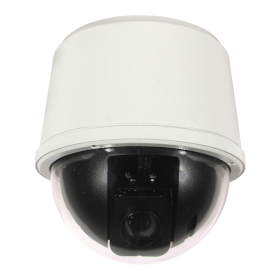
360 Vision VisionDome VR Panduan Instalasi & Konfigurasi - Halaman 11
Jelajahi secara online atau unduh pdf Panduan Instalasi & Konfigurasi untuk Kamera Keamanan 360 Vision VisionDome VR. 360 Vision VisionDome VR 20 halaman.

Vision i Dome_VisionDome VR Installation Manual Ver 3.1
Internal Vision i Dome/VisionDome Connections
The connection board is located at the top of the dome.
A Twisted Pair Video balun is required to suit cable length to receive video signal.
Coax Video Connection board
Power Connections
Connect 24Vac to CON2.
Data Connections
Connect RS485 (D+/D-) to Dome connection board using CON3.
Video Connections
Connect Video Coax cable (Video/Gnd) to Dome connection board
using CON4.
Active Balun Twisted Pair Video Board
(Screw Terminal version)
Power Connections
Connect 24Vac to CON4.
Data Connections
Connect RS485 (D+/D-) to Dome connection board using CON8.
Video Connections
Connect Twisted Pair Video Signal cable (V+/V-) to Dome
connection board using screw terminal CON5. A Twisted Pair Video
balun is required to suit cable length to receive video signal.
Active Balun Twisted Pair Video Board
(RJ45 Connector version)
Power Connections (if Required)
Connect 24Vac to CON4.
LK1 & LK2 can be used to switch power into the camera from the
RJ45 (CON3) to the two way screw connector (CON4).
Power, Video & Data Connections
Connect cable to RJ45 CON3. (Twisted Pair Video Signal Only). A
Twisted Pair Video balun is required to suit cable length to receive
video signal. Wiring/connection diagram shown below.
RJ45
CAT5, CAT5e, CAT6 Cable
Pin 1
White with Orange Band
Pin 2
Pin 3
White with Green Band
Pin 4
Pin 5
White with Blue Band
Pin 6
Pin 7
White with Brown Band
Pin 8
RJ45 CON3 Connections
© 360 Vision Technology Ltd.
Orange
Blue
Green
Brown
Signal
Video +
Video -
RS485 D+
AC+
AC+
RS485 D-
AC-
AC-
Page 11
