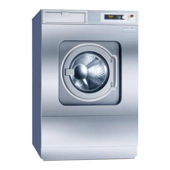
Miele PW 6241 Panduan Petunjuk Pengoperasian - Halaman 40
Jelajahi secara online atau unduh pdf Panduan Petunjuk Pengoperasian untuk Mesin cuci Miele PW 6241. Miele PW 6241 46 halaman.
Juga untuk Miele PW 6241: Petunjuk Pengoperasian dan Pemasangan (44 halaman), Petunjuk Pengoperasian dan Pemasangan (44 halaman), Manual Petunjuk Pemrograman (48 halaman)

Notes for the installer
Electrical connection
The electrical connection must only be
carried out by a suitably qualified electrician
in accordance with local and national safety
regulations (BS 7671 in the UK).
When installing a residual current device
(RCD), this must be a Type B RCD (suitable
to detect high frequency AC and DC earth
leakage current).
The electrical components of machines PW
6241and PW 6321 comply with EN 60335-1
and EN 60335-2-7.
The connection points are located behind a
cover.
The machine is supplied ex-works for 3N AC
50-60 Hz. See data plate for details.
It is also available in the following
versions:
3 N AC 380-415 V 50-60 Hz
3 AC 220-240 V 50-60 Hz
Connection should be made via a suitable
isolator which complies with local and
national safety regulations and which is
easily accesible for disconnecting the
machine from the electricity supply.
Provision must be made on site to switch off
all poles. Switches with a minimum all-pole
contact gap greater than 3 mm are suitable
for isolating the machine. These include
circuit breakers, fuses and relays (IEC/EN
60947).
The isolator switch should be easily
accessible for servicing work.
40
If the machine is disconnected from the
electricity supply ensure adequate measures
are taken to ensure that the machine cannot
be reconnected to the electricity supply until
all work has been carried out.
Equipotential bonding
Equipotential bonding must be carried out if
required.
The electric heating is set ex-works to
24 kW (PW 6241), 30 kW (PW 6321).
The heating will only be activated with a
minimum suds levels of 110 mm column of
water.
The motor is protected by a winding to
prevent it overheating.
Connection should be made in accordance
with the wiring diagram and the installation
diagram to a suitable isolator, with an on-off
switch which is easily accessible for
servicing. The wiring and installation
diagrams are important for the correct
electrical functioning of the machine.
Connecting the dispenser pumps
Connection points for 4 time controlled
dispenser pumps which can be operated
without the multi-function module are located
behind the cover next to the electrical
connection point. See the wiring diagram
supplied.
M.-Nr. 06 572 495
