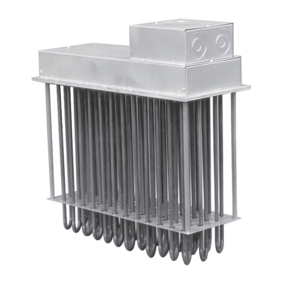
Chromalox ADHT-060 Panduan Petunjuk Instalasi - Halaman 6
Jelajahi secara online atau unduh pdf Panduan Petunjuk Instalasi untuk Pemanas Chromalox ADHT-060. Chromalox ADHT-060 12 halaman. Air duct heaters adh series; adht series
Juga untuk Chromalox ADHT-060: Identifikasi Suku Cadang Pemasangan, Pengoperasian, dan Pembaruan (8 halaman)

Wiring
ELECTRIC SHOCK HAZARD. Any installation involv-
ing electric heaters must be performed by a quali-
fied person and must be effectively grounded in
accordance with the National Electrical Code to
eliminate shock hazard.
1. All wiring should be done in accordance with National
Electrical Code and with local codes by a qualified per-
son.
2. Connect air heaters to same line voltage, phase, and fre-
quency as on heater nameplate.
3. Teflon insulated nickel plated copper wire or bus bar is
recommended for power connections to heater terminals
and for wiring runs in heated zones. When ambient tem-
perature in heated zone exceeds that for which insulated
wire is recommended use bare nickel-plated copper with
porcelain beads, tubing or bus bar. Consult local Chro-
malox representative.
4. Users should install adequate back-up controls and safe-
ty devices with their electric heating equipment. Selec-
tion of controls, thermostat, SCR units, contactors and
etc. depends on the degree of accuracy required, reli-
ability, electrical rating of heater and economic consider-
ations.
ADH-015, 15 kW 480V 3ø, 1 Circuit
(9) - 480V, 1667 Watt Elements
Control
Voltage
120 or 240V
Figure 8
Operation
Do not operate heater at voltages in excess of that stamped
on the heater since excess voltage will shorten heater life.
Maintenance
ELECTRIC SHOCK HAZARD. Disconnect all power
before installing or servicing heater. Failure to do so
could result in personal injury or property damage.
Heater must be installed by a qualified person in ac-
cordance with the National Electrical Code, NFPA
70.
Fused
Switch
L
1
L
2
L
3
Thermostat
Control Switch
5. Below is an example of a standard ADH-015, 480V 3 Ø
15 kW, wired with recommended back-up controls. (Fig-
ure 8)
6. Individual terminal blocks with 1/4-20 threaded stud type
terminals are provided for each circuit to permit quick
positive attachment of circuit wiring conductors (one ter-
minal block per circuit). (Figure 9)
Terminal block
(303-027852-001)
X Circuit label indicated here.
Figure 9=
Magnetic
Contactor
Terminal
Block
L
1
L
2
L
3
Customer Supplied Wiring
Factory Supplied Wiring
1. Periodically clean terminals and terminal covers of dust
and corrosion to maintain good electrical connections
and to permit rapid heat dissipation. Use airblast, and be
careful to avoid damage to mica insulation.
2. Check for loose terminal connections. Tighten as neces-
sary.
6
3
ADH-015
