Chromalox CXH-A/B-07S Petunjuk Pemasangan, Pengoperasian, dan Pemeliharaan - Halaman 15
Jelajahi secara online atau unduh pdf Petunjuk Pemasangan, Pengoperasian, dan Pemeliharaan untuk Pemanas Chromalox CXH-A/B-07S. Chromalox CXH-A/B-07S 18 halaman. Hazardous location forced-air heater
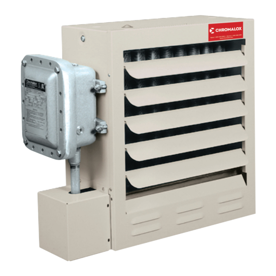
Replacing Motor and/or Fan Blade
1. Disconnect the unit from power supply.
2. (Units with motor splice box) Remove 4 bolts and cover
of motor splice box
3. (See Figure 12). (Units without motor splice box) Remove
16 bolts and cover of main control enclosure.
4. Note wire connections for future reference and discon-
nect all wires leading to the motor. All motor wires are
permanently marked according to the nameplate on the
motor.
5. Remove 4 bolts in motor base holding it to rear cabinet
shelf.
6. Remove 4 screws holding fan guard to cabinet.
7. Unthread union at motor wiring outlet nipple connection.
Carefully lift the motor, fan blade, and guard off of the
cabinet.
8. Note position of fan blade on motor shaft. Loosen the
two set screws to remove the fan blade and key from
shaft motor.
9. Place guard and fan blade on replacement motor shaft in
same locations as original motor. Align key ways in hub
and shaft. Insert key flush with fan hub and tighten the
two hub set screws.
10. Feed motor wires back into conduit and reposition motor
back on unit. Center fan blade in opening and rotate to
be sure that it clears housing and guard.
11. Thread motor nipple connection into conduit union and
tighten (5 threads minimum). Replace bolts in motor base
and reattach fan guard to back of housing in four places.
Recheck blade rotation and tighten all hardware.
12. Trim all motor leads extending out of the conduit to 6
lengths. Strip off 3/8" of insulation at cut ends. Using the
motor nameplate, previous notes, and marked wires, re-
connect the motor for the unit voltage rating as indicated
on the heater nameplate. Reattach the ground wire to
the connection inside the enclosure. Replace cover and
tighten securely.
13. Check fan rotation by momentarily energizing the unit. Air
must exit at cabinet front. Reverse any 2 leads at contac-
tor or line supply disconnect to reverse rotation of three
phase motor.
14. Removal of fan blade does not require that the motor
wiring be disturbed. To clean, service or change the fan
blade proceed as follows:
A. Remove the four carriage bolts holding the motor base
in place on the cabinet platform. Mark the platform to
reposition at same location.
B. Loosen the four screws on the cabinet back holding
the fan guard in place.
C. Pull the motor to the rear extending the conduit con-
nection at the electrical enclosure. Fan blade and hub
set screws can now be accessed by tilting the guard
rearward at top or bottom back over the motor shell.
Motor Bolt Removal
Motor Splice Block
15