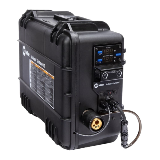
Miller ArcReach SuitCase Non-CE Panduan Pemilik - Halaman 25
Jelajahi secara online atau unduh pdf Panduan Pemilik untuk Sistem Pengelasan Miller ArcReach SuitCase Non-CE. Miller ArcReach SuitCase Non-CE 48 halaman.

5-7.
Connecting Welding Gun And Voltage Sensing Clamp
7
3
10
�
Complete Parts List is available at www.MillerWelds.com
4
2
1
6
5
8
7
1 Gun Locking Tab In Place
2 Gun Locking Tab Out Of Place
3 Gun Securing Knob
4 Gun Block
5 Gun Power Pin
6 Power Pin Groove
Ref. 256617-A / 278800-A
7 Gun Locking Tab
Loosen gun securing knob, insert gun power
pin into gun block. Position power pin as
close as possible to drive rolls without touch-
ing. Align the gun power pin groove with the
gun locking tab. Tighten gun securing knob.
If the gun power pin does not have a groove,
loosen knob to rotate the gun locking tab 180
degrees. This prevents the the gun locking
tab from interfering with the gun power pin
when inserted into the gun block. Insert the
gun power pin into the gun block. Position
power pin as close as possible to drive rolls
without touching them. Tighten gun securing
knob.
8 Gun Trigger Plug
9 Gun Trigger Receptacle
Connect gun trigger plug to gun trigger
receptacle.
See Section 6-4 to make wire speed dual
schedule
receptacle.
9
10 Voltage Sensing Clamp
Connect
workpiece.
Turn Off wire feeder and welding
power source. Stop engine on
welding generator.
Weld voltage is present at voltage
sensing clamp when wire feeder
and welding power source are on.
This condition exists even if wire
feeder light and meters are off.
Turn off wire feeder or welding
power source before handling or
moving voltage sensing clamp.
connections
to
gun
voltage
sensing
clamp
OM-278792 Page 19
trigger
to
