Miller S-74 MPa Plus Panduan Pemilik - Halaman 31
Jelajahi secara online atau unduh pdf Panduan Pemilik untuk Aksesori Pengelasan Miller S-74 MPa Plus. Miller S-74 MPa Plus 48 halaman.

8-1.
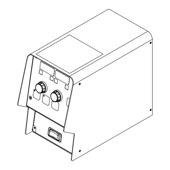
Setup Menu
To enter the SETUP MENU press and re-
lease the SETUP button. The SETUP
MENU INDICATOR and the SETUP BUT-
TON INDICATOR will illuminate.
Rotate the LEFT ADJUST KNOB to select
different menu items shown in the LEFT
DISPLAY. Rotate the RIGHT ADJUST
KNOB to change menu item values shown
in the RIGHT DISPLAY.
To exit the SETUP MENU press and release
the SETUP button.
Items that can be adjusted in this menu are:
Trigger Control (TRIG) - Sets the gun trig-
ger control. The trigger control can be con-
figured as (STD, HOLD, or SPOT).
Trigger Hold Delay (HOLD) - Additional
trigger setting only appearing in the menu
when the trigger control is set to (TRIG
HOLD). Trigger hold delay time is the mini-
mum amount of time the trigger must be
held for trigger hold to become active. There
is a built in maximum trigger hold time which
the trigger must be released within for trig-
ger hold to become active. The maximum
trigger hold time is always 4.0 seconds after
the trigger hold delay time. For Example, if
the trigger hold delay time is set to 2.0 sec-
onds, the trigger must be held for at least
2.0 seconds and released within 6.0 sec-
onds for trigger hold to become active. Once
the trigger hold function is active, the wire
feeder will continue feeding wire until the
trigger is pressed and released again.
Trigger 4T - Allows the operator to select
between weld parameters and crater param-
eters using the gun trigger. Crater time must
be set for at least 0.2 seconds to make this
function operational. If gun trigger is
SECTION 8 – PROGRAMMING
released during welding the unit goes into
trigger hold - pressing and holding trigger
again will cause the unit to stay in crater until
trigger is released and crater parameter
times out.
Trigger Spot Time (SPOT) - Additional trig-
ger setting only appearing in the menu when
the trigger control is set to (TRIG SPOT).
The SPOT time is the length of combined
time for the start (if applicable) and the weld
sequence. The weld will end when the set
time has expired or the trigger has been re-
leased, whichever occurs first. The spot time
is reset when the trigger is released.
Remote Process Select - For MIG (MIG)
operation, the Left Display always shows
Voltage. For Pulsed MIG (PULS) operation,
the Second Level Setup Menu Display
(PULS) option selects whether Voltage
(VOLT) or Arc Length (ARC. L) is shown in
the Left Display.
�
A Remote Process Select capable
power source automatically switches
to the selected weld process when this
option is changed at the wire feeder.
The wire and gas program selections
for each weld process must be set at
the power source.
�
When Trigger Schedule Select (see
Section 8-2) is enabled, the Weld
Process option can be set independ-
ently for each schedule. This allows
the operator to remotely change the
weld process at the wire feeder and
power source with a single tap of the
welding gun trigger.
Preflow (PRE) - The amount of time that the
shielding gas will flow after the trigger is
pressed and before the welding arc will be
allowed to be active. Range of this setting is
from (0.0 to 5.0) seconds.
Postflow (POST) - The amount of time that
the shielding gas will flow after the arc has
been shut off. Range of this setting is from
(0.0 to 10.0) seconds.
Run-In Speed (R-IN) - The wire feed speed
prior to the welding arc being struck. This
setting is a percentage of the wire feed
speed the unit is set to for welding. Range of
this setting is from (X0.10 to X0.99 to OFF).
Example: If the weld wire speed is 200 and
R-IN is X0.50, the run-in wire speed is 100.
Burnback (B. BAK) - Burnback sets a time
from 0 to 0.25 seconds in increments of 0.01
seconds. This is the time that the arc is al-
lowed to stay on after the wire stops
feeding.
Burnback Volts (VLTS) - Sets the voltage
used for burnback. The range is the same
as the selected power source. Measured in
0.1 volt increments.
Retract (RTRK) - When enabled, the user
can set a distance in inches from 0 to 1.5 in-
ches. This is the distance the wire will back-
up after welding stops.
Profile Pulse ON/OFF - When Profile Pulse
is On, the pulse parameters and wire speed
are coordinated to produce a consistent rip-
ple pattern.
�
Additional PROFILE PULSE menu
items may appear in the SETUP
MENU when PROFILE PULSE is ac-
tive. See Section 8-7.
OM-289404 Page 25
